Removable mounting bracket

a tubular bracket and mounting bracket technology, applied in the direction of roofs, cycle equipments, doors, etc., can solve the problems of mirror loss, and achieve the effect of easy and rapid installation and removal, strong connection, and strong construction

Active Publication Date: 2007-09-11
COVIELLO RANDY
View PDF15 Cites 13 Cited by
  • Summary
  • Abstract
  • Description
  • Claims
  • Application Information

AI Technical Summary

Benefits of technology

[0007]It is the primary object of this invention to provide a side view mirror mounting bracket that is sturdy in construction, has a sturdy connection to the supporting vehicle when in its position of use, and is easily and rapidly installed and removed. It is also an object of this invention to provide a side view mirror mounting bracket structure that is not likely to scratch the paint of the vehicle during its attachment or removal, or during its use. A further object of this invention is to provide a side view mirror mounting bracket structure that has a uniform and aesthetically appealing look with the vehicle to which it is attached. It is also an object of this invention to provide a side view mirror mounting bracket structure that can be easily connected upside down relative to the vehicle for rock climbing applications, such as but not limited to monitoring the amount of clearance under the vehicle. It is a further object of this invention to provide a side view mirror mounting bracket structure that has durable construction and requires little refurbishment between uses. A further object of this invention is to provide a side view mirror mounting bracket structure that can be used to mount devices other than mirrors to a motor vehicle after its doors have been removed.

Problems solved by technology

However, such an attachment means is weak, and during off-road adventures can result in the loss of the mirror.

Method used


Image

  • Removable mounting bracket
  • Removable mounting bracket
  • Removable mounting bracket

Examples


Embodiment Construction

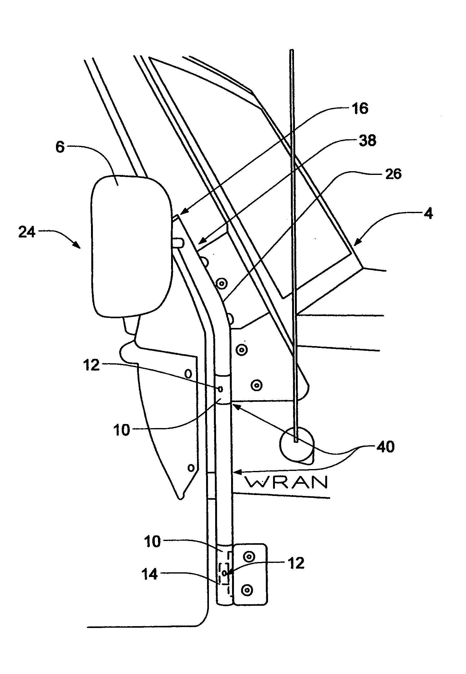
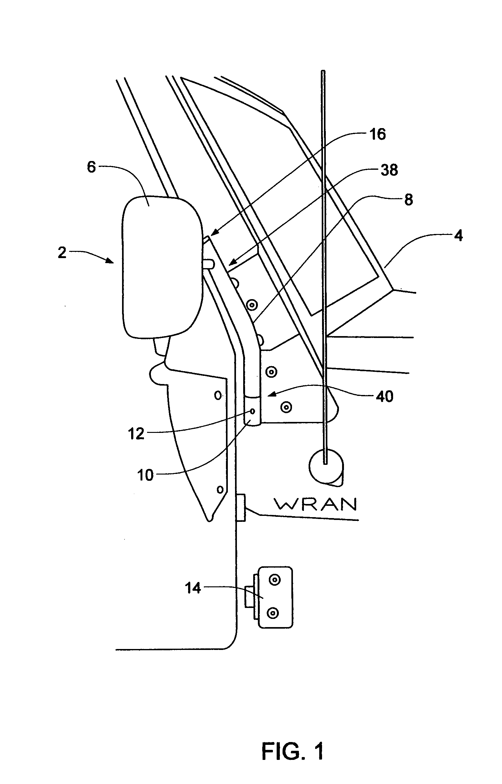
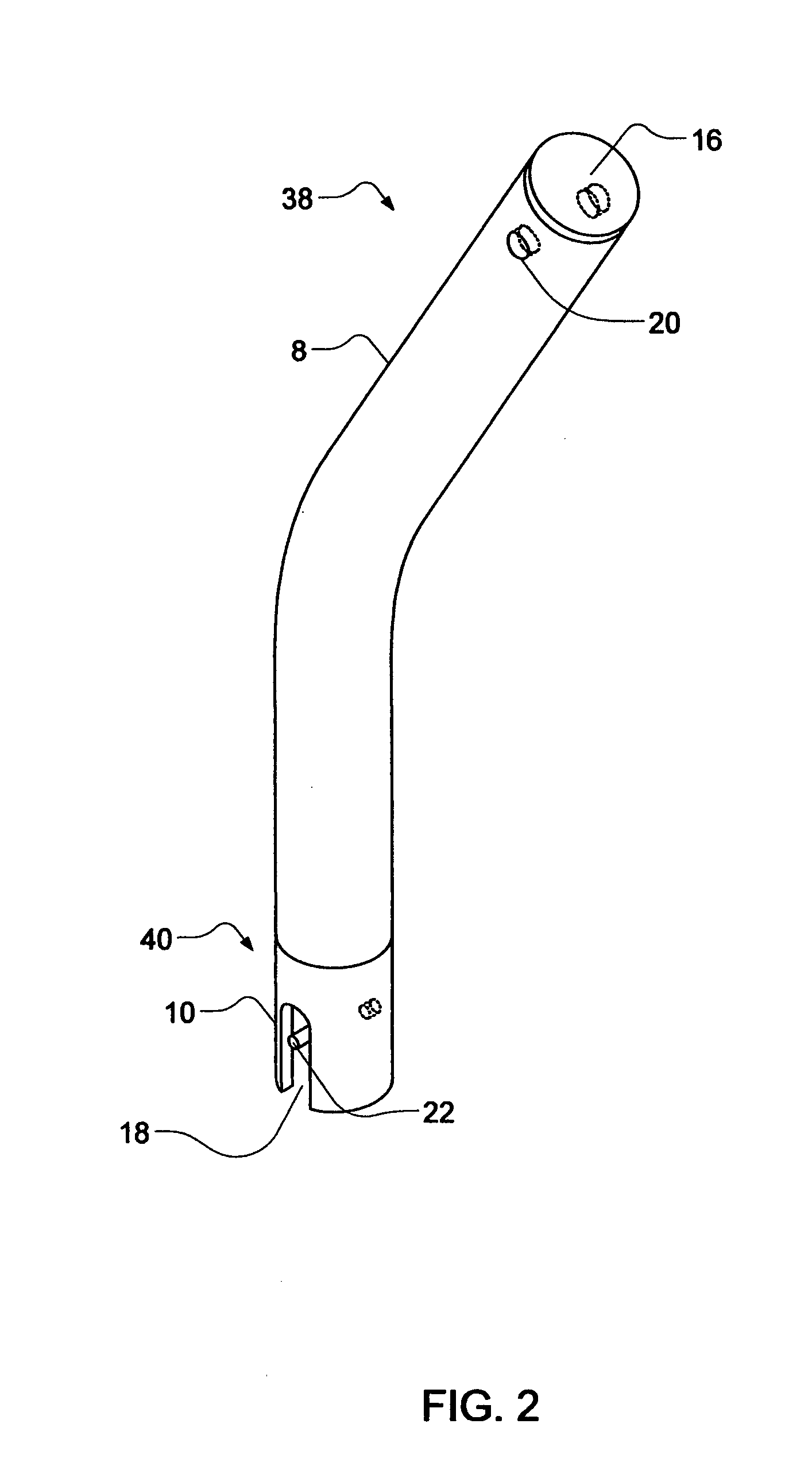
[0020]FIGS. 1-8 show three preferred embodiments of the present invention and optional accessories employed to enhance its use. FIGS. 1-3 show a first preferred embodiment 2 of the present invention having a short tubular mounting bracket 8 with a distal end 38 and a proximal end 40, while FIGS. 4-5 shows a second preferred embodiment 24 of the present invention having an elongated tubular mounting bracket 26 with an elongated proximal end 40 that slides over and covers two vertically spaced-apart door hinges 14 on vehicle 4. In addition, FIG. 6 shows an end cap 16 for sealing the top of the distal end 38 of tubular mounting bracket 8, FIG. 7 shows a plug 30 with an internally threaded bore 32 that is employed to expand within a second open mirror mounting hole 20 after a first fastening means 9 in the form of either a hex headed bolt, a machine threaded screw (Phillips, slotted, or Allen tipped hole), or similar fastener has passed through the open distal end 38, been inserted thro...


PUM


Abstract

A quickly installed and quickly removable tubular mounting bracket that supports a side view mirror and is connected at a minimum to the upper hinge structure remaining on the side of the vehicle after the door is removed. On two-door 4×4 off road vehicles commonly referred to as JEEP, two hinge members remain after a door is removed, one above the other and set at a spaced-apart distance from one another, and the present invention can be manufactured to engage one or both of them. The mounting bracket herein further has an angle that follows the angle of the windshield for aesthetic, practical, and aerodynamic purposes, with the mounting of the brackets used for securing driver and passenger mirrors to the vehicle without doors being slightly different from one another to provide optimum driver visibility.

Description

CROSS-REFERENCES TO RELATED APPLICATIONS[0001]The subject matter of the instant patent application has previously been disclosed in two Document Disclosures filed with the U.S. Patent & Trademark Office by the same inventor herein on Jun. 1, 2004, which have assigned Serial Numbers respectively of 554222 and 554223. Since the two Document Disclosures have been on record in the U.S. Patent & Trademark Office for a time period of less than two years, all benefit thereof is herein requested.BACKGROUND[0002]1. Field of the Invention[0003]This invention relates to a means of mounting side view mirrors on a motor vehicle in the absence of its doors, specifically to a quickly installed and quickly removable tubular bracket that supports a side view mirror and is connected at a minimum to the upper hinge structure remaining on the side of the vehicle after the door is removed. On two-door 4×4 off road vehicles commonly referred to as JEEP, two hinge members remain after a door is removed, o...

Claims


Application Information

Patent Timeline
Patent Type & Authority Patents(United States)
IPC IPC(8): B60J1/20
CPCB60R1/078
Inventor COVIELLO, RANDY
Owner COVIELLO RANDY
Why Eureka
Try Eureka