
Human body supporting structure, particularly bicycle saddle and method of making same

a human body and supporting structure technology, applied in the field of sport and leisure, can solve the problems of poor cost-effectiveness, excessive weight of final product, and difficult implementation of methods, and achieve the effect of high efficiency and cost-effectiveness

Active Publication Date: 2012-03-06
SELLE ROYAL SPA
View PDF10 Cites 15 Cited by
  • Summary
  • Abstract
  • Description
  • Claims
  • Application Information

AI Technical Summary

Benefits of technology

The solution results in a lighter, more cost-effective, and sturdy support structure with enhanced mechanical properties, enabling the production of efficient and repeatable manufacturing processes for human body supporting products.

Problems solved by technology

First, the method is of very difficult implementation, because the apertures of the various sheet elements have to match almost perfectly.
Furthermore, an adequate mechanical strength can be only obtained by laying a considerable number of sheet elements one above the other, wherefore the final product is excessively heavy and poorly cost effective.

Method used


Image

  • Human body supporting structure, particularly bicycle saddle and method of making same
  • Human body supporting structure, particularly bicycle saddle and method of making same
  • Human body supporting structure, particularly bicycle saddle and method of making same

Examples


first embodiment

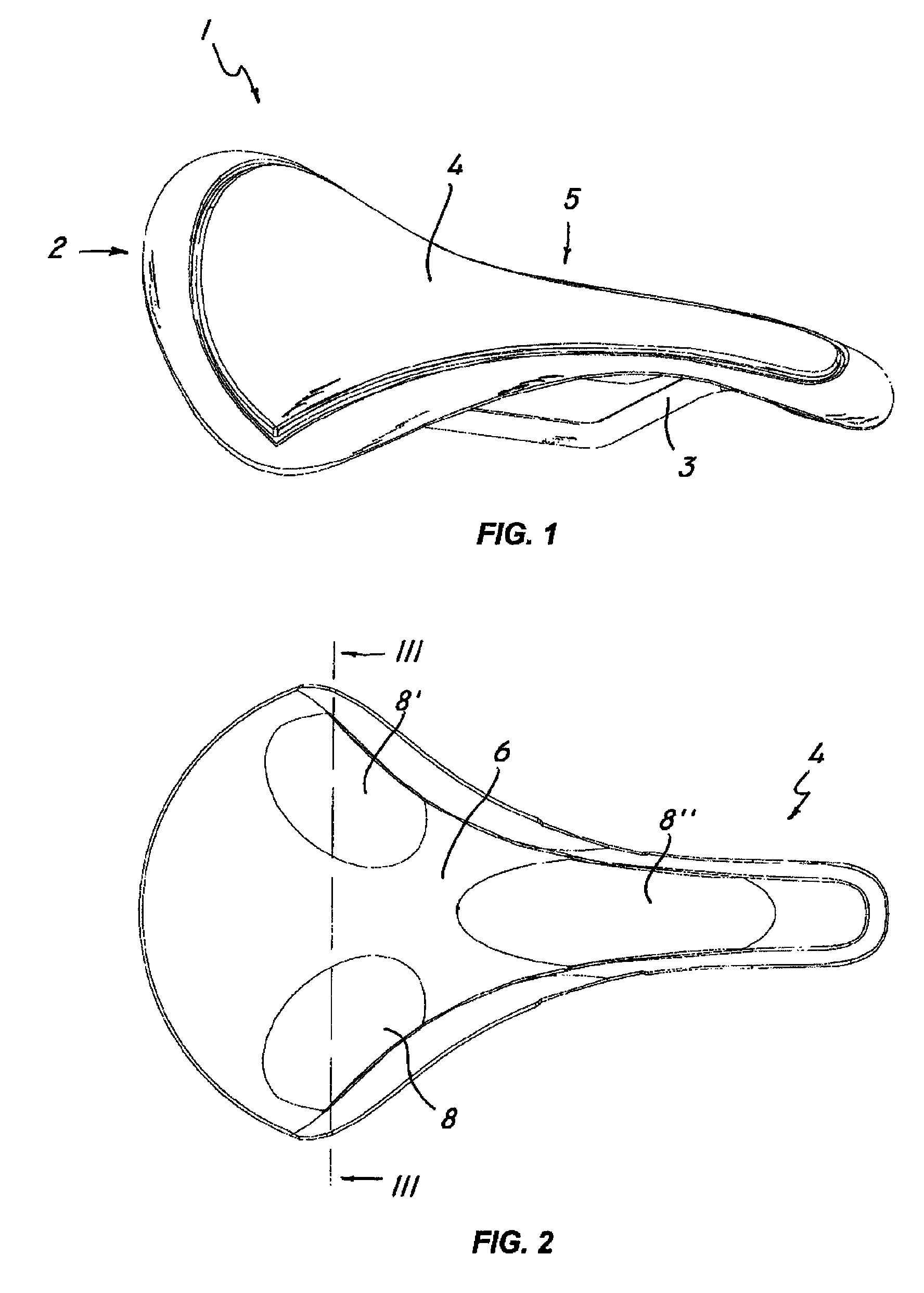
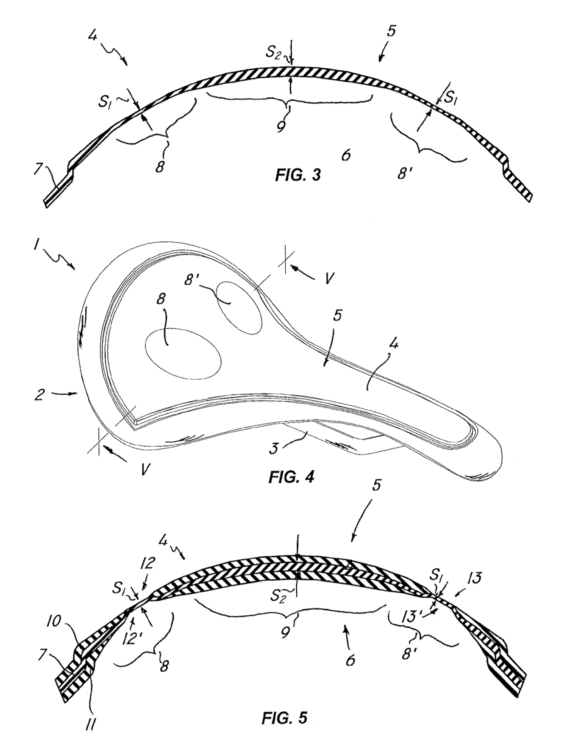
[0040]FIG. 3 shows the invention, in which the shell 4 is made up of one sheet element 7 only. Nevertheless, it shall be understood that the shell 4 may also consist of multiple sheet elements of the same type, without departure from the inventive scope as defined in the annexed claims. This embodiment includes three differently deformable portions, with the first two portions, designated by numerals 8, 8′ being formed at the ischial area and the other, designated by numeral 8″, being formed at the prostatic area.

[0041]In this embodiment, the thickness S1 of the differently deformable area 8 is smaller than the thickness 52 of the other areas of the sheet element 7, e.g. the central area 9. Also, the average density ρ1 of the differently deformable portion 8 is greater than the average density ρ2 of the central area 9. The combination of these two characteristics will impart a higher deformability to the differently deformable portion 8 as compared to that of the central portion 9, ...

second embodiment

[0042]FIG. 5 shows the invention, in which the shell 4 is formed of a continuous sheet element 7 interposed between two discontinuous sheet elements 10, 11 having apertures 12, 12′ and 13, 13′ coincident with the differently deformable portions 8, 8′.

[0043]In this embodiment, the thickness S1 of the differently deformable area 8 is smaller than the thickness S2 of the other areas of the sheet element 7, e.g. the central area 9. Also, the average density ρ1 of the differently deformable portion 8 is greater than the average density ρ2 of the central area 9.

[0044]Advantageously, the discontinuous sheet elements 10, 11 may be formed of the same material as the continuous sheet element 7 and may have a different color from the latter, to create a pleasant color effect.

[0045]The ratio between the average thickness S1 of the continuous sheet element 7 at the differently deformable portion 8 and the average thickness S2 of the rest of the extension thereof may fall in a range from 0.1 to 0...


PUM

PropertyMeasurementUnit
thicknessaaaaaaaaaa
densityaaaaaaaaaa
mechanical strengthaaaaaaaaaa

Abstract

A human body supporting structure, particularly a bicycle saddle, includes a load-bearing shell having a topside designed to face towards a user and an underside designed to face a bicycle frame. The shell includes at least one continuous sheet element having at least one differently deformable portion located at particularly stressed regions of the user's body. The sheet element is formed of a thermoplastic resin matrix with reinforcement fibers embedded therein. The differently deformable portions have a smaller thickness (Si) and a locally greater average density (pi) than the rest of the extension of the shell, said portions are formed in a thermoforming step wherein a local thickness reduction is carried out by compression and by heating said sheet element to a temperature near the melting temperature of the thermoplastic matrix. A method of making such support structure is further provided.

Description

BACKGROUND[0001]1. Technical Field[0002]The present invention finds application in the art of sport and leisure and particularly relates to a human body supporting structure and a method of making same.[0003]Particularly, a human body supporting structure may be a bicycle saddle, a seating surface of a chair, a human body protection device, a shoe insole, a helmet, a glove and the like.[0004]2. Description of Related Art[0005]Human body supports, particularly bicycle saddles, are known to include a shell for supporting a user's weight. Certain types of supports are further known to include a load-bearing shell having one or more differently deformable portions, i.e. having a higher resilience as compared with the rest of the shell.[0006]These higher resilience portions, usually located in the areas of contact between the shell and certain sensitive areas of the user, may be formed using a variety of methods.[0007]EP1305203, in the name of the same applicant, discloses a bicycle sadd...

Claims


Application Information

Patent Timeline
Patent Type & Authority Patents(United States)
IPC IPC(8): B62J1/00
CPCB62J1/007
Inventor SEGATO, STEFANO
Owner SELLE ROYAL SPA
Learn More