Bistable electric switch and relay with a bi-stable electrical switch

a bi-stable, electric switch technology, applied in the direction of relays, snap-action arrangements, protective switch details, etc., can solve the problems of additional drive elements and extremely complicated spring construction

Inactive Publication Date: 2005-09-13
TE CONNECTIVITY GERMANY GMBH
View PDF18 Cites 31 Cited by
  • Summary
  • Abstract
  • Description
  • Claims
  • Application Information

AI Technical Summary

Benefits of technology

[0018]It is furthermore of particular advantage to provide auxiliary contacts which ensure that the flow of current through the wires made from shape memory material is interrupted as soon as the switch-over movement occurs. This enables the wires to be charged with a current which, when flowing continuously through the wires, would lead to destruction of the wires but which, on account of the short duration of the flow of current, does not lead to destruction of the wires. Such high strengths of current in the control circuit allow a quick switch-over, as is typical for relays.
[0019]It is of particular advantage to use a switch according to the invention as a relay.
[0020]It

Problems solved by technology

The disadvantage of this configuration is that it requires a relatively large space, the con

Method used


Image

  • Bistable electric switch and relay with a bi-stable electrical switch
  • Bistable electric switch and relay with a bi-stable electrical switch
  • Bistable electric switch and relay with a bi-stable electrical switch

Examples


first embodiment

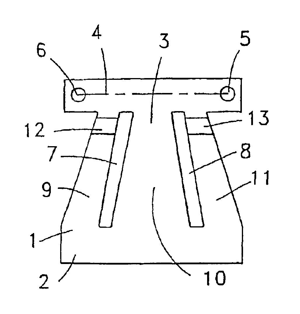
[0043]FIGS. 1 to 4 show a spring for a bi-stable electric switch according to the invention. Spring 1 is a bi-stable nonlinear snap-action spring that is configured as a trapezoid. It has a wide side 2 as well as a narrow side 3. Again arranged on the narrow side 3 is a carrier strip 4 to which the contact elements are also secured on the regions 5 or 6 by riveting or welding.

[0044]The spring is subdivided into three plates 9, 10 and 11 by means of two oblique elongated slots 7 and 8. The plates 9, 10 and 11 are connected to one another at their ends. The lateral plates 9 and 10 are plastically deformed as a result of bending by means of a crimp 12 and 13. The crimp is located near the narrow side 3 of the trapezoidal spring. Because of the crimps 12 and 13, the plates 9 and 11 are shortened and as a result exert a pressure on the middle plate 10. The plate 10 relieves the pressure as it bulges to one side. This can be seen particularly clearly in FIG. 2. The position of the crimp i...

third embodiment

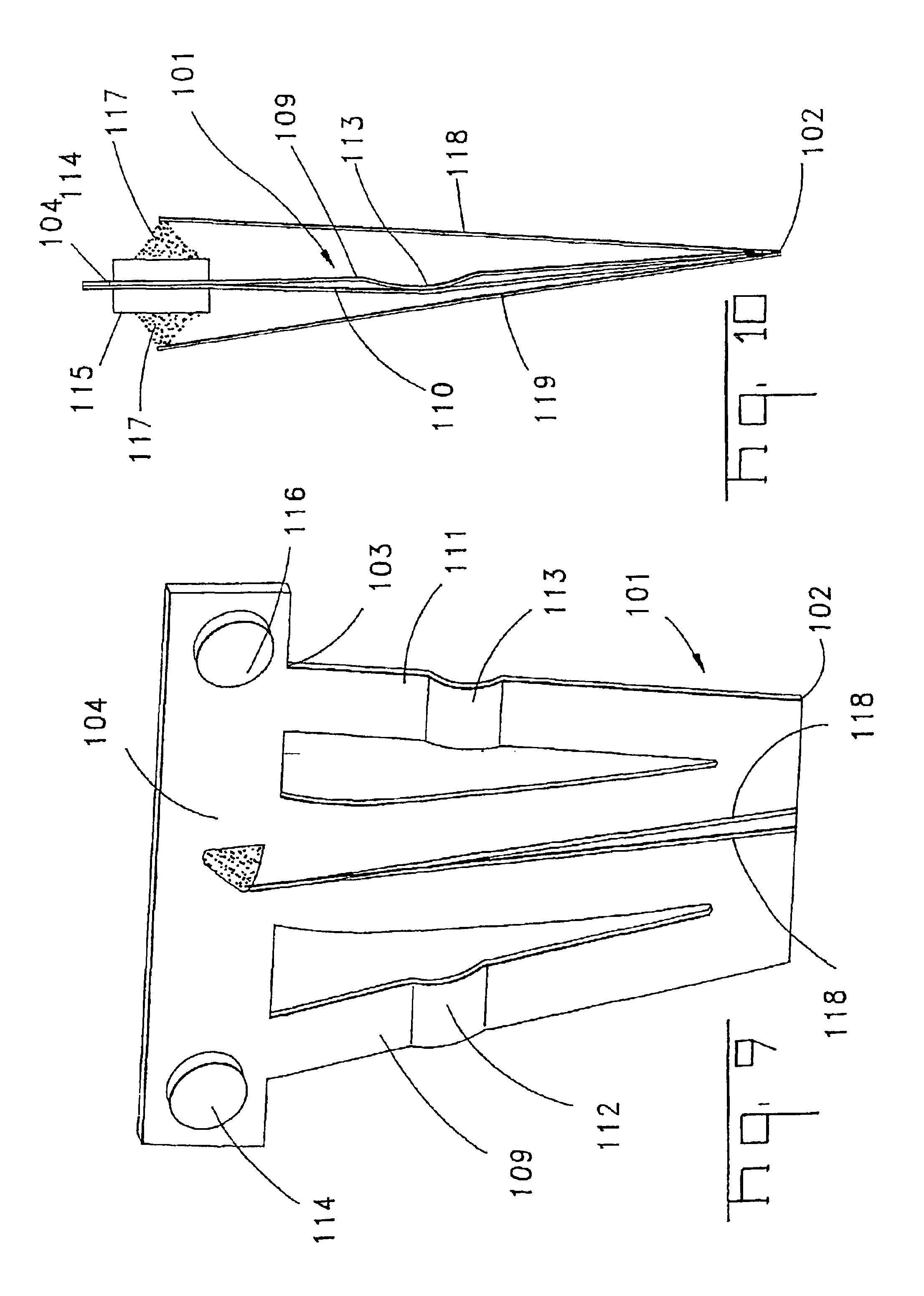
[0048]A trapezoidal spring 101 is also shown in the third embodiment shown in FIGS. 9 and 10; it is, however, rigidly fixed with its narrow side 102. A carrier strip 104 is located on its wide side 103 and carries the contact elements 114, 115 and 116. The trapezoidal spring 101 also has a middle plate 110 as well as two lateral plates 109 and 111 that are in each case shortened by means of a crimp 112 and 113.

[0049]There is a short lever arm 117 on the carrier strip 4 on each side. A wire 118 and 119 is sometimes secured to this. If a current flows through such a wire 118 or 119, the wire heats up and as a result enters into its second shortened phase. Because of this shortened phase the carrier strip 114 is then tilted and this tilting causes the bulge of the middle plate 110 to snap over from one side to the other side and as a result the trapezoidal spring 101 is transferred into its second stable final state.

[0050]Although the heating occurring when the current flows through th...


PUM


Abstract

The invention relates to a bi-stable electric switch comprising a spring (101) that is configured as a bi-stable snap-action spring and carries contact elements (114, 116) on the carrier strip (104) of the spring and comprising at least one drive element made from shape memory material per switch state for actuating the spring, the spring having a plate (110) that is rigidly fixed at one end (102) and that is subjected to a pressure in the direction of its linear extension and evades this by bulging towards one side into one of two stable final states, the regions of the spring in the stable final states taking up different lateral positions and the drive elements (118, 119) acting upon the free end of the plate and as a result of the tilting of free end (104) cause it to snap into the second stable final state.

Description

FIELD OF THE INVENTION[0001]The invention relates to a bi-stable electric switch comprising a spring that is configured as a bi-stable snap-action spring and carries contact elements on at least one region of the spring and comprising at least one drive element made from shape memory material per switch state for actuating the spring. In addition the invention relates to a relay with such a bi-stable electric switch.BACKGROUND OF THE INVENTION[0002]A switch consisting of a drive element, a spring contact and first and second wires made from shape memory material as well as first and second contact elements is known from U.S. Pat. No. 5,990,770. The drive element has a substantially T-shaped configuration and is pivoted at the foot of the T. Wires made from shape memory material are arranged at both ends of the cross of the T, the length of which changes depending on the temperature, it being possible to change the temperature by means of a current flowing through the wires. As a res...

Claims


Application Information

Patent Timeline
IPC IPC(8): H01H61/00H01H61/01H01H5/00H01H5/18H01H61/04H01H37/32
CPCH01H61/0107H01H5/18H01H2061/0122H01H1/26
Inventor HANKE, MARTINKROEKER, MATTHIASHAEHNEL, THOMASSCHULTHEISS, JOERG
Owner TE CONNECTIVITY GERMANY GMBH
Why Eureka
Try Eureka