Fiber optic connector tray system

a fiber optic connector and tray technology, applied in the direction of optics, fibre mechanical structures, instruments, etc., can solve the problems of compromising transmission effectiveness and efficiency

Inactive Publication Date: 2005-09-13
TELECT
View PDF50 Cites 101 Cited by
  • Summary
  • Abstract
  • Description
  • Claims
  • Application Information

AI Technical Summary

Problems solved by technology

Because of the very delicate and exacting nature of optical fibers, it is important that the individual fibers not be overly...

Method used


Image

  • Fiber optic connector tray system
  • Fiber optic connector tray system
  • Fiber optic connector tray system

Examples


Embodiment Construction

)

[0025]Many of the fastening, connection, manufacturing and other means and components utilized in this invention are widely known and used in the field of the invention described, and their exact nature or type is not necessary for an understanding and use of the invention by a person skilled in the art or science; therefore, they will not be discussed in significant detail. Furthermore, the various components shown or described herein for any specific application of this invention can be varied or altered as anticipated by this invention and the practice of a specific application or embodiment of any element may already be widely known or used in the art or by persons skilled in the art or science; therefore, each will not be discussed in significant detail.

[0026]The terms “a”, “an”, and “the” as used in the claims herein are used in conformance with long-standing claim drafting practice and not in a limiting way. Unless specifically set forth herein, the terms “a”, “an”, and “the...


PUM


Abstract

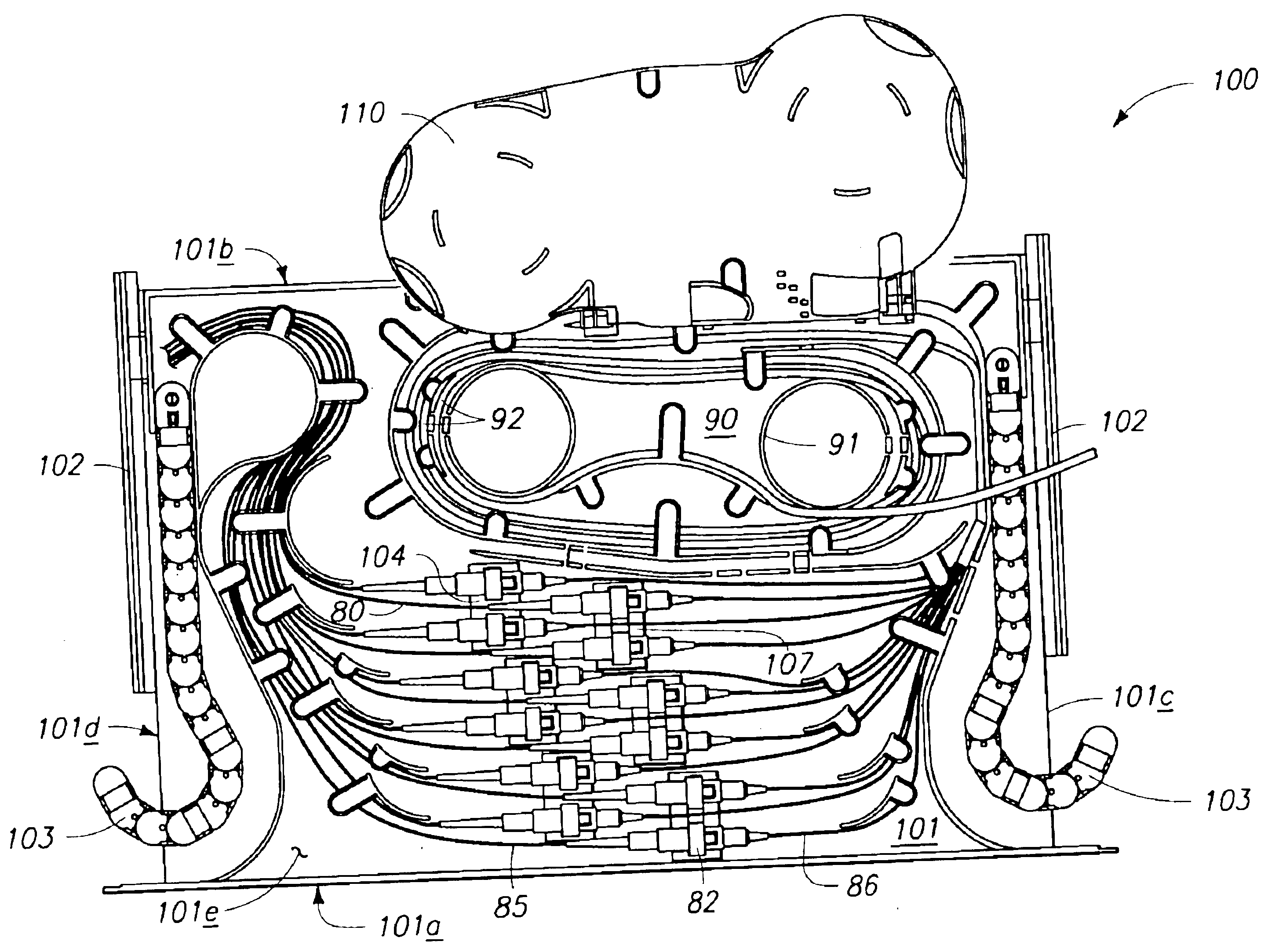
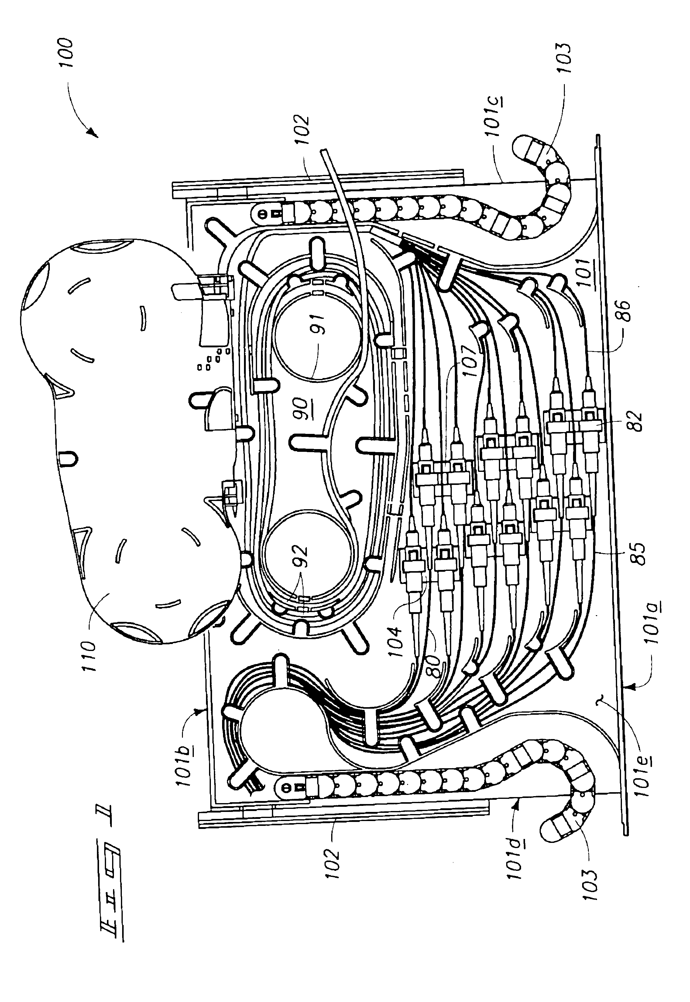
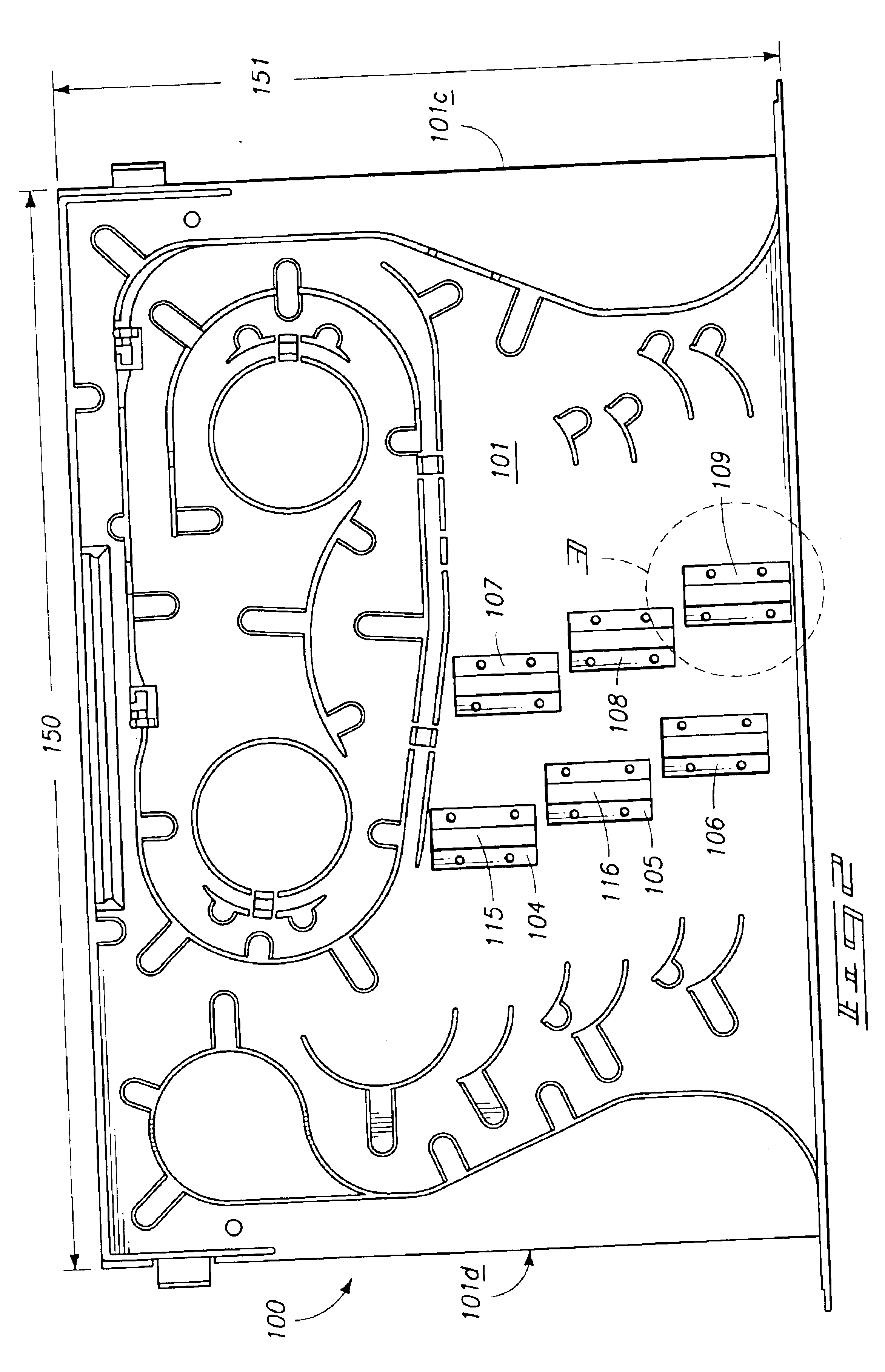
A fiber optic cable connector tray system with a tray framework with a first end, a second end, a first side and a second side, a plurality of fiber optic cable adapter holders mounted to the tray framework such that fiber optic connectors therein would be in a generally transverse orientation from the first side to the second side of the tray framework, the plurality of fiber optic cable adapter holders each having a first adapter mount area configured to receive a first adapter; a second adapter mount area configured to receive a second adapter; and a fiber optic cable passageway between the first adapter mount area and the second adapter mount.

Description

TECHNICAL FIELD[0001]This invention pertains to fiber optic connector tray system primarily for use in telecommunications facilities, more particularly, a fiber optic connector tray system which includes a high density of adapter holders and a high density of fiber optic cable adapters and connectors with and without a storage area and / or a splice housing.BACKGROUND OF THE INVENTION[0002]With the large increase in demand for telecommunications capacity, there is an increasing need for greater density and capacity in all areas of telecommunications, including signal transmission, connections or cross-connections, and terminations. The better utilization of a given amount of space in telecommunications facilities is becoming more and more important.[0003]In many facilities there are bays or racks in which different types of cabinets and other equipment are mounted. Generally a telecommunication fiber optic cable distribution bay or panel is located in the central office of a telephone...

Claims


Application Information

Patent Timeline
IPC IPC(8): G02B6/38G02B6/44
CPCG02B6/3825G02B6/4455G02B6/4461G02B6/3878G02B6/3897G02B6/4452
Inventor HOWELL, BRET L.POSHUSTA, PAUL N.
Owner TELECT
Why Eureka
Try Eureka