
Method and device for detecting an interference condition

a technology of interference condition and detection method, which is applied in the direction of instruments, wireless communication, transmission, etc., can solve the problems of burdening processor and memory, causing errors, and causing significant errors in position at the gps receiver

Active Publication Date: 2005-09-13
GOOGLE TECH HLDG LLC
View PDF13 Cites 16 Cited by
  • Summary
  • Abstract
  • Description
  • Claims
  • Application Information

AI Technical Summary

Problems solved by technology

Jamming interference from a variety of sources can disrupt the process of finding and decoding GPS signals, which can cause errors.
These errors may build up if jamming continues.
As a result of these jamming-induced built up errors, significant errors in position may occur at the GPS receiver.
This requires extensive use of the Fast Fourier Transform (FFT), which burdens the processor and memory of a receiver as the FFT output over multiple time intervals must be stored during the processing of information.

Method used


Image

  • Method and device for detecting an interference condition
  • Method and device for detecting an interference condition
  • Method and device for detecting an interference condition

Examples


Embodiment Construction

[0017]In the following detailed description of exemplary embodiments of the invention, reference is made to the accompanying drawings, which illustrate specific exemplary embodiments in which the invention may be practiced. These embodiments are described in sufficient detail to enable those skilled in the art to practice the invention, but other embodiments may be utilized and logical, mechanical, electrical and other changes may be made without departing from the scope of the present invention. The following detailed description is, therefore, not to be taken in a limiting sense, and the scope of the present invention is defined only by the appended claims.

[0018]In the following description, numerous specific details are set forth to provide a thorough understanding of the invention. However, it is understood that the invention may be practiced without these specific details. In other instances, well-known circuits, structures and techniques have not been shown in detail in order ...


PUM


Abstract

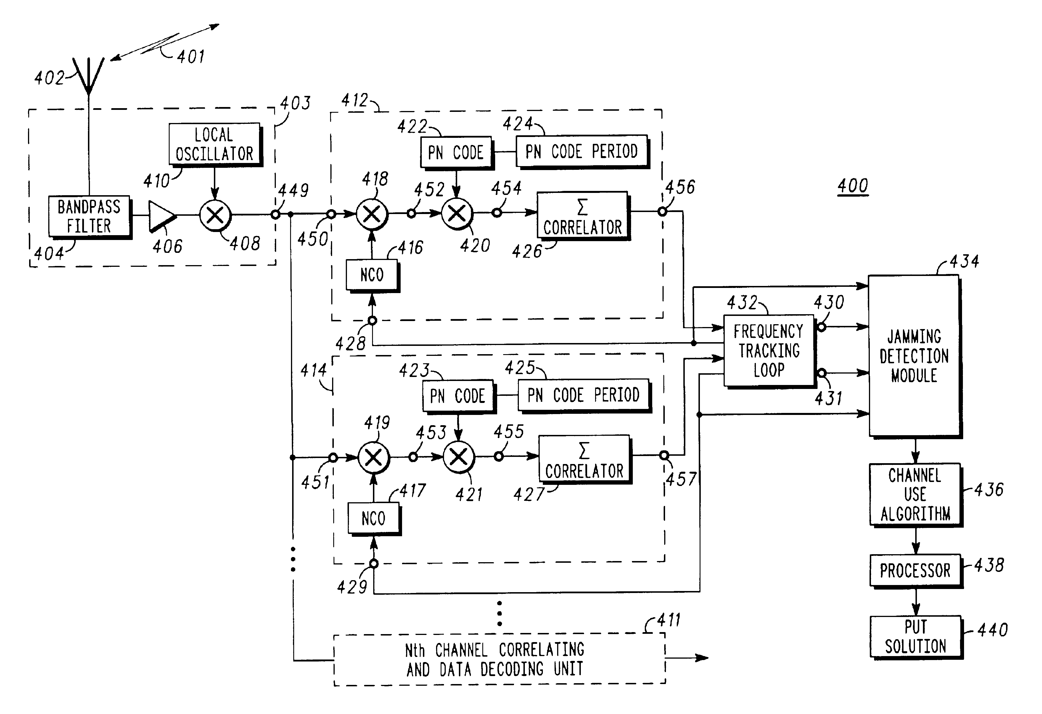
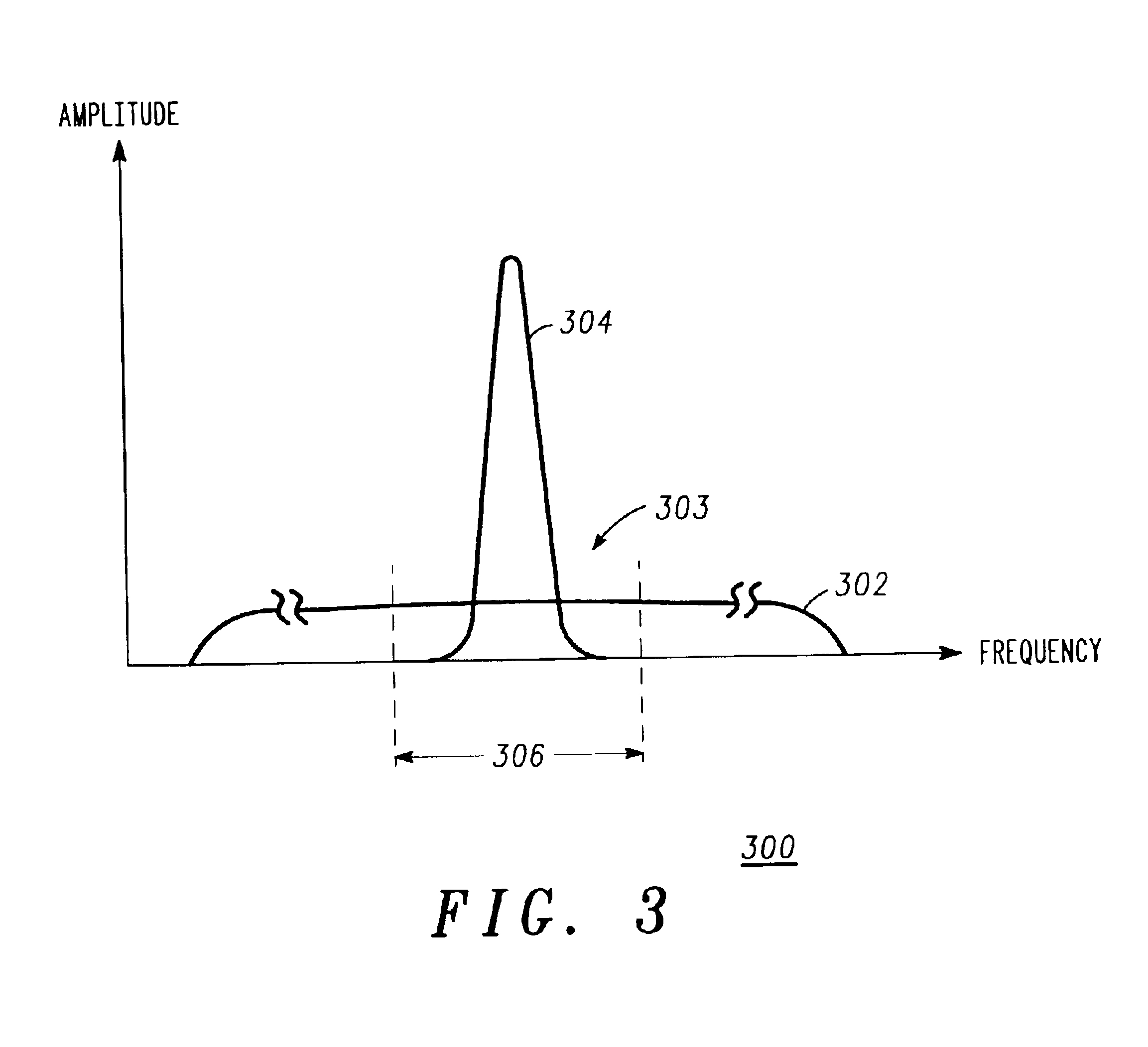
A method of detecting a jamming signal (304) in a wireless device (102) includes providing a plurality of channels (401), wherein each of the plurality of channels has an NCO frequency (428, 429), and receiving a channel lock indicator (430, 431) for each of the plurality of channels. A jamming signal is detected if the NCO frequency of each of the plurality of channels differs by an integer multiple of an inverse of a pseudorandom noise code period (424, 425). A wireless device includes a plurality of channels, wherein each of the plurality of channels has an NCO frequency. A frequency tracking loop for each of the plurality of channels outputs a channel lock indicator for each of the plurality of channels. A jamming detection module receives the channel lock indicator and the NCO frequency from each of the plurality of channels. The jamming detection module detects an interference condition if the NCO frequency of each of the plurality of channels differs by an integer multiple of an inverse of a pseudorandom noise code period.

Description

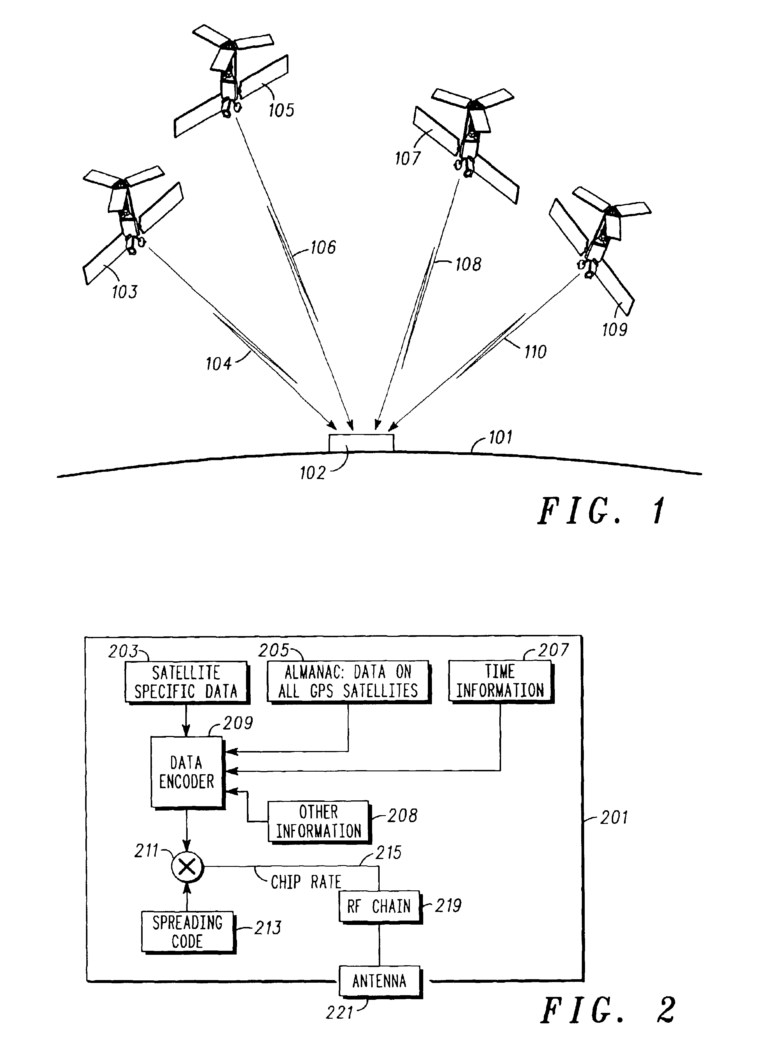
BACKGROUND OF THE INVENTION[0001]The Global Positioning System (GPS) is a satellite based navigation system having a network of 24 satellites orbiting the earth 11,000 nautical miles in space, in six evenly distributed orbits. Each satellite orbits the earth every twelve hours. A prime function of the GPS satellites is to serve as a clock. Each satellite derives its signals from an onboard 10.23 Mega Hertz (MHz) Cesium atomic clock. Each satellite transmits a spread spectrum signal with its own individual pseudorandom noise (PN) code. By transmitting several signals over the same spectrum using distinctly different pseudorandom noise coding sequences the satellites may share the same bandwidth without interfering with each other. These coding sequences are a time series of bits, called “chips”. The code used in the non-military portion of the GPS system is 1023 chips long and is sent at a rate of 1.023 megachips per second yielding a time mark (i.e. a “chip”) approximately once ever...

Claims


Application Information

Patent Timeline
IPC IPC(8): H04Q7/20H04K3/00H04B1/10G01S1/00G01S19/21G01S19/26
CPCG01S19/21H04K3/224H04K3/90
Inventor FITRANDOLPH, DAVID K.
Owner GOOGLE TECH HLDG LLC
Learn More