AI technical title is built by Patsnap AI team. It summarizes the technical point description of the patent document.
a fuel cell and manifold technology, applied in the field of fluid flow in manifolds, can solve the problems of inapplicability to metal/air fuel cells, high complexity, and undesirable variations in fluid concentration and/or flow rate, and achieve the effect of reducing the number of manifolds
Inactive Publication Date: 2005-09-20
TECK COMINCO METALS LTD
View PDF15 Cites 24 Cited by
Summary
Abstract
Description
Claims
Application Information
AI Technical Summary
This helps you quickly interpret patents by identifying the three key elements:
Problems solved by technology
Method used
Benefits of technology
Benefits of technology
[0021]In a further aspect, the invention pertains to use of invention methods in suitable systems. Exemplary suitable systems include without limitation fuel cell subsystems, fuel cells, internal combustion engines, and the like, and suitable combinations of any two or more thereof. In any such system, the invention assists in the uniform delivery of each of the components of a single flow of a single or multiphase fluid to a plurality of destinations to which uniform delivery of at least one of the components is desired.
Problems solved by technology
However, one skilled in the art will readily recognize the geometric complexity that this technique introduces into the system after the second stage.
Such complexity is not practical for use in a metal / air fuel cell, which requires a more compact arrangement of parallel flow paths in order to integrate the manifold within a portable stacked cell design.
Multiphase fluid flow through such a manifold will typically produce undesirable variations in the fluid concentration and / or flow rate of the dispersed phase of the multiphase fluid.
The differences in pressure drops can cause differences in flow rates (e.g., velocities), and thus can result in differences in the flow rates of the dispersed phase.
Further, these differences in flow rates can result in different drag forces, and thus can result in different concentrations of the dispersed phase.
Method used
Image
Click on the blue label to locate the original text in one second.
Reading with bidirectional positioning of images and text.
Examples
example 1
Making of a Manifold
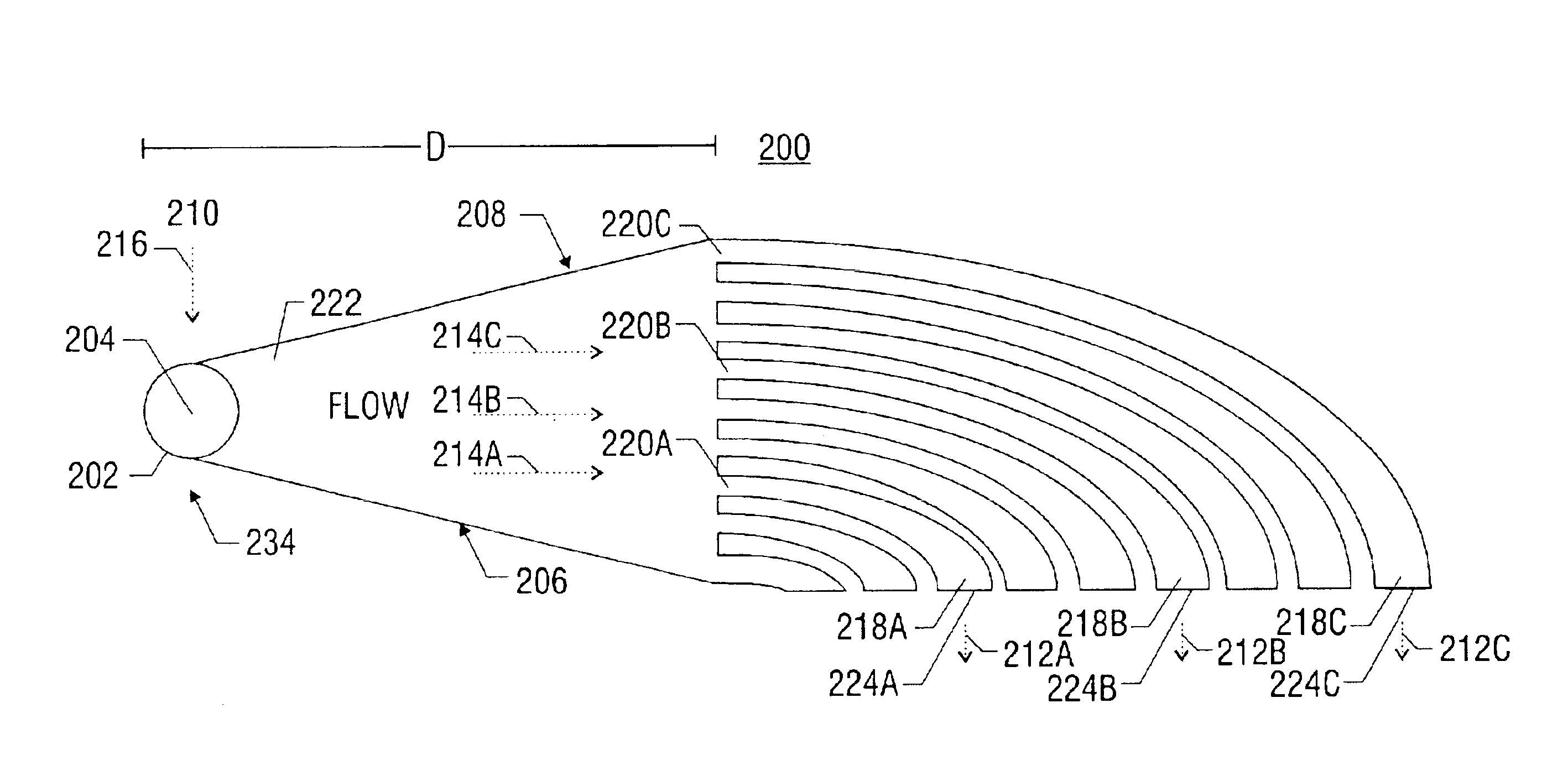
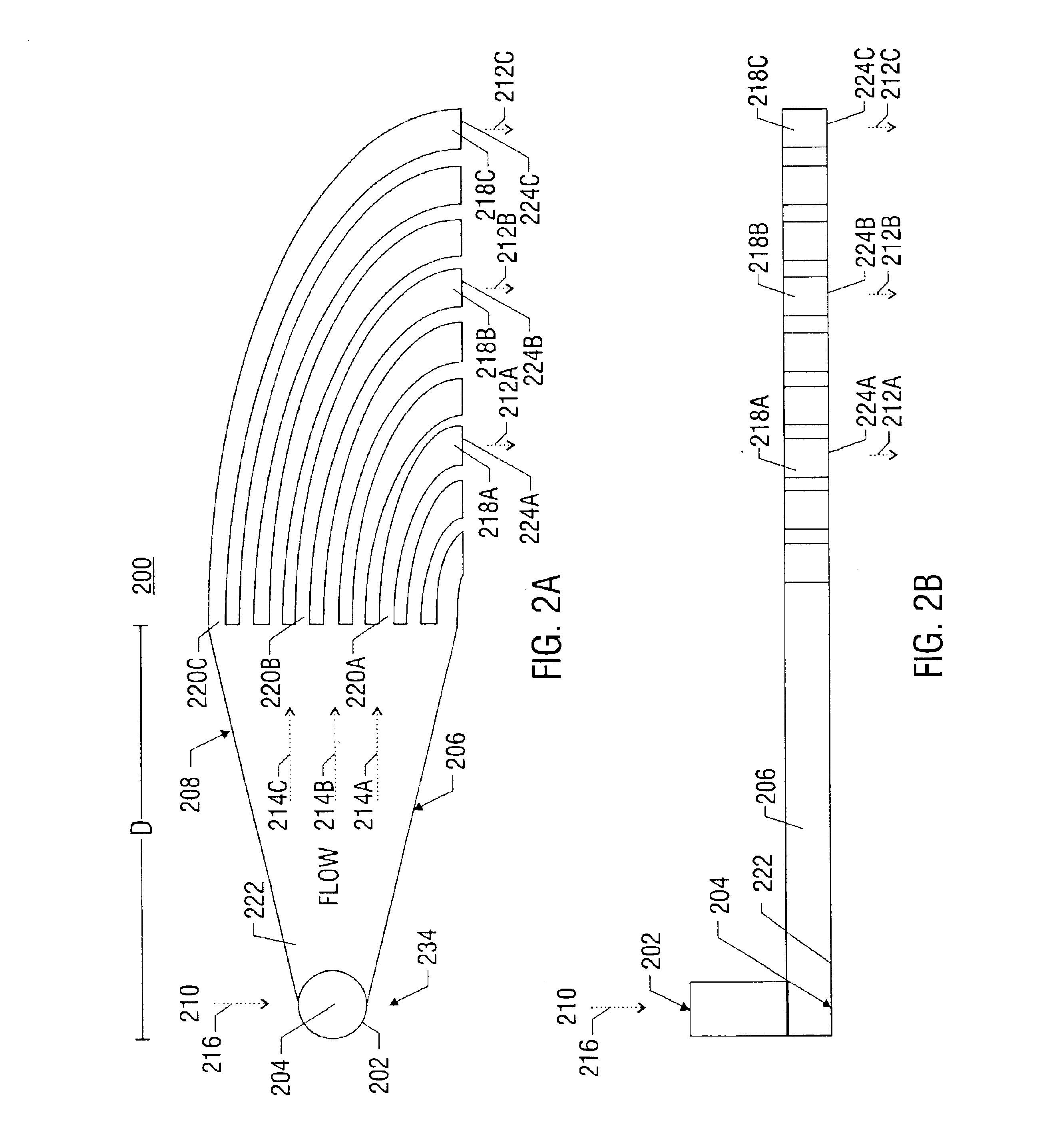
[0106]A manifold can be constructed in accordance with the invention as follows. With reference to FIG. 2a, a manifold 200 can be constructed to comprise an inlet 202 for a single flow of a multiphase fluid (e.g., solid zinc particles in a KOH liquid solution). The manifold is constructed so that the single flow impacts the base surface 204 of the inlet 202 at a 90 degree angle to the flow at a point on the base surface (e.g., the stagnation point), and can thus generate a plurality of redirected flows moving radially outward from the stagnation point and perpendicular to the original single flow. Two walls of the manifold, 206 and 208, capture only a portion of the plurality of redirected flows and further guide this portion across a predetermined distance from the stagnation point to the inlets of nine separate channels. In the case of a manifold having 9 channels, each comprising a 3 mm×10 mm rectangular cross section, and a 1 mm spacing between adjacent condu...
PUM
Property
Measurement
Unit
angle of incidence
aaaaa
aaaaa
angle of incidence
aaaaa
aaaaa
angle
aaaaa
aaaaa
Abstract
A method and apparatus for converting single multiphase fluid flow into plural multiphase fluid flows having substantially uniform composition and flow properties. A manifold comprises an enclosure having an inlet and an inner surface perpendicular to the inlet such that the incident angle of input flow impacts the surface to form a stagnation point whereby an intermediate flow is deflected along the surface substantially symmetrically outward from the stagnation point and channeled to a plurality of parallel fluid outlets connected to the enclosure. The distance between the stagnation point and the plurality of outlets is selected to maintain substantially equivalent fluid pressures and uniform flow rates at the outlets. A preferred embodiment of the manifold channels the intermediate flow between two walls forming a triangular shaped nozzle directing the flow from the stagnation point to the base of the triangle for communication of electrolyte to a metal-based fuel cell through the plurality of outlets.
Description
[0001]This application is a continuation-in-part of U.S. patent application Ser. No. 10 / 072,856, filed Oct. 19, 2001 now U.S. Pat. No. 6,679,280, which is hereby fully incorporated by reference herein as though set forth in full.RELATED APPLICATIONS[0002]This application is related to U.S. patent application Ser. No. 09 / 930,557, entitled “POWER SYSTEM INCLUDING HEAT REMOVAL UNIT FOR PROVIDING BACKUP POWER TO ONE OR MORE LOADS,” filed Aug. 15, 2001; U.S. patent application Ser. No. 09 / 930,394, entitled “METAL FUEL CELL SYSTEM FOR PROVIDING BACKUP POWER TO ONE OR MORE LOADS,” filed Aug. 15, 2001; U.S. Provisional Application No. 60 / 318,685, entitled “ULTRA-LONG DURATION BACKUP FOR CRITICAL APPLICATIONS USING ZINC / AIR REGENERATIVE FUEL CELLS,” filed Sep. 10, 2001; U.S. Provisional Application No. 60 / 328,838, entitled “ULTRA-LONG DURATION BACKUP FOR TELECOMMUNICATIONS APPLICATIONS USING ZINC / AIR REGENERATIVE FUEL CELLS,” filed Oct. 11, 2001, U.S. patent application Serial No. 09 / 973,490...
Claims
Application Information
Patent Timeline
Application Date:The date an application was filed.
Publication Date:The date a patent or application was officially published.
First Publication Date:The earliest publication date of a patent with the same application number.
Issue Date:Publication date of the patent grant document.
PCT Entry Date:The Entry date of PCT National Phase.
Estimated Expiry Date:The statutory expiry date of a patent right according to the Patent Law, and it is the longest term of protection that the patent right can achieve without the termination of the patent right due to other reasons(Term extension factor has been taken into account ).
Invalid Date:Actual expiry date is based on effective date or publication date of legal transaction data of invalid patent.

