Staggered opposite jetting air film hole row structure used for turbine blade leading edge air film cooling

A turbine blade and air film cooling technology, which is applied in the direction of blade support components, engine components, machines/engines, etc., can solve the problems of difficulty in machining and poor heat insulation effect of inclined cylindrical hole rows in the same direction, and achieve low cost, The effect of easy processing

Inactive Publication Date: 2015-08-12
NORTHWESTERN POLYTECHNICAL UNIV
View PDF6 Cites 12 Cited by
  • Summary
  • Abstract
  • Description
  • Claims
  • Application Information

AI Technical Summary

Problems solved by technology

[0003] In order to avoid the deficiencies of the existing technology and overcome the disadvantages of difficult processing of the traditional same-direction inclined cylindrical hole row a

Method used


Image

  • Staggered opposite jetting air film hole row structure used for turbine blade leading edge air film cooling
  • Staggered opposite jetting air film hole row structure used for turbine blade leading edge air film cooling
  • Staggered opposite jetting air film hole row structure used for turbine blade leading edge air film cooling

Examples


Embodiment 1

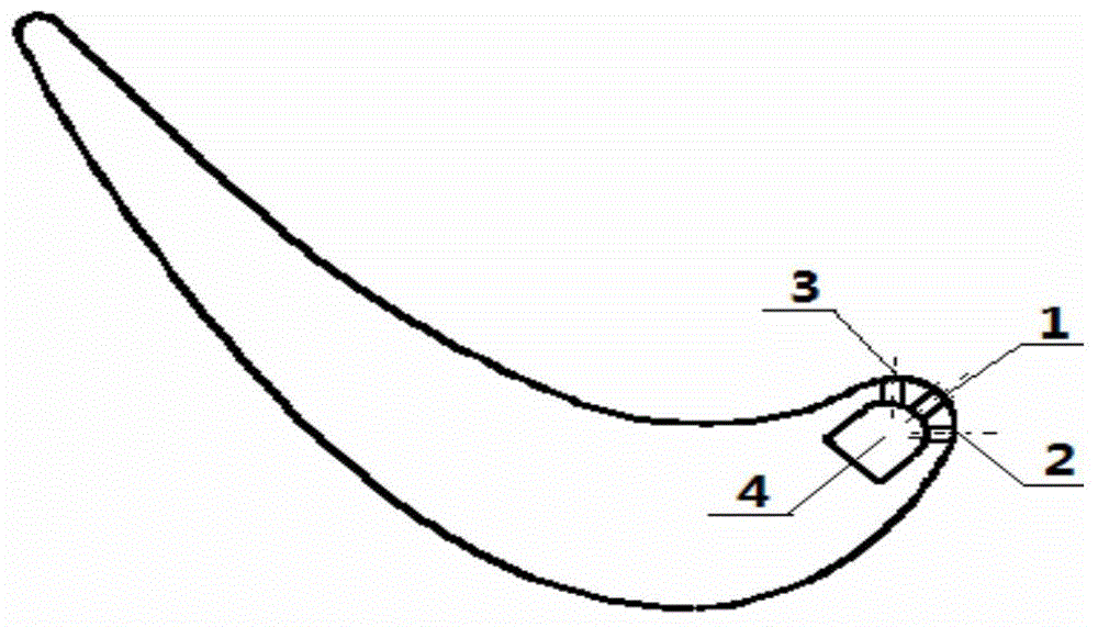
[0021] In this embodiment, the leading edge region of the turbine blade of a certain type of gas turbine is provided with a structure of dislocation opposing gas film holes. The opened air film hole is a cylindrical hole, and the cross-sectional shape of the air film hole changes from the entrance of the air film hole to the exit of the air film hole. The air film hole is inclined along the radial direction of the turbine blade. The inclination angles of half of the gas film holes are the same, but the inclination directions are opposite, and the center line of the upper half of the gas film holes and the center line of the lower half of the gas film holes are misaligned along the blade flow direction, forming a structure of dislocation pairs of punching holes.

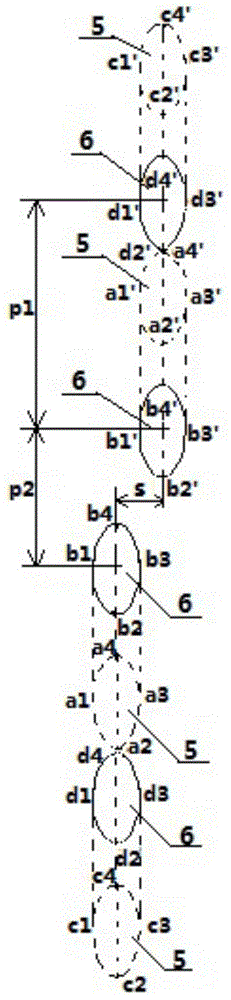
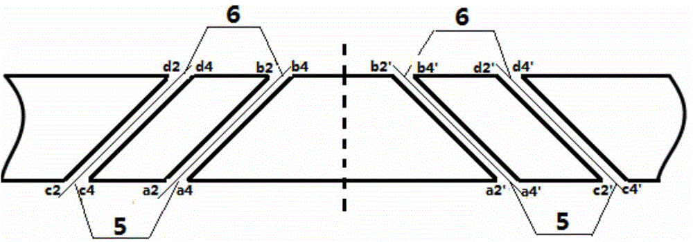
[0022] The four vertices of the elliptical inlet of the film hole: a1, a2, a3, a4 correspond to the four vertices of the elliptical outlet: b1, b2, b3, b4, the side wall surface of the hole, including the surface a1-a2...

Embodiment 2

[0026] In this embodiment, the leading edge region of the turbine blade of a certain type of gas turbine is provided with a structure of dislocation opposing gas film holes. The air film holes opened are cylindrical holes, and the air film holes are inclined radially along the turbine blade. The inclination angles of the upper half of the air film holes and the lower half of the air film holes in the same row are the same, but the inclination direction is opposite, and the upper half The center line of part of the air film hole and the center line of the lower half of the air film hole are misaligned along the flow direction of the blade, forming a structure of misaligned pairs of punching holes.

[0027] The four vertices of the elliptical inlet of the film hole: a1, a2, a3, a4 correspond to the four vertices of the elliptical outlet: b1, b2, b3, b4, the side wall surface of the hole, including the surface a1-a2-b2-b1- a1, surface a1-a4-b4-b1-a1, surface a2-a3-b3-b2-a2, and s...

Embodiment 3

[0031] In this embodiment, the leading edge region of the turbine blade of a certain type of gas turbine is provided with a structure of dislocation opposing gas film holes. The air film holes opened are cylindrical holes, and the air film holes are inclined radially along the turbine blade. The inclination angles of the upper half of the air film holes and the lower half of the air film holes in the same row are the same, but the inclination direction is opposite, and the upper half The center line of part of the air film hole and the center line of the lower half of the air film hole are misaligned along the flow direction of the blade, forming a structure of misaligned pairs of punching holes.

[0032] The four vertices of the elliptical inlet of the film hole: a1, a2, a3, a4 correspond to the four vertices of the elliptical outlet: b1, b2, b3, b4, the side wall surface of the hole, including the surface a1-a2-b2-b1- a1, surface a1-a4-b4-b1-a1, surface a2-a3-b3-b2-a2, and s...


PUM


Abstract

The invention discloses a staggered opposite jetting air film hole row structure used for turbine blade leading edge air film cooling. Air film cooling hole rows are processed in a turbine blade leading edge area. The suction surface staggered opposite jetting air film hole row and the pressure surface staggered opposite jetting air film hole row are arranged at the two sides of the blade leading edge stagnation point staggered opposite jetting air film hole row. The cross section shape of each air film hole is changed from the cross section shape of the air film hole inlet to that of the air film hole outlet, and the air film holes are communicated with the cold channels the turbine blades. The radial inclination angle of the air film holes is 25-60 degrees; the aperture of the air film holes is 0.3-0.8mm; the radial hole spacing of the inclination holes in the same direction in the air film hole rows is 3d-9d; the flow direction distance between the center lines of the staggered air film holes in the air film hole rows is 0.5d-d; and the radial distance between the two adjacent staggered air film holes is 3d-9d. According to the staggered opposite jetting air film hole row structure, a relatively stable air film coverage area is enabled to be formed on the wall surface of the blade leading edge by the jetted cold air so that the air film cooling effect is improved; besides, the staggered opposite jetting air film hole row structure has the characteristics of being easy and convenient to process and low in cost.

Description

technical field [0001] The invention relates to the technical field of turbine blades of gas turbines, in particular to a structure of dislocated opposite gas film hole rows for gas film cooling at the leading edge of a turbine blade. technical background [0002] Air film cooling is a cooling technology applied to the blades of gas turbines, that is, the high-pressure cold air is extracted from the last stage of the compressor and transported to the inner channel of the blade. The air film hole is sprayed out, and the cold air bends downstream under the action of the mainstream and the fluid Coanda effect, and adheres to the wall surface to form a cold air film with a lower temperature, which isolates the wall surface from the high-temperature gas and takes away part of the high-temperature gas. The radiant heat of gas or bright flame to the wall surface plays a good protective role, so as to achieve the purpose of preventing the blades from being burned by high-temperature...

Claims


Application Information

Patent Timeline
IPC IPC(8): F01D5/18
Inventor 刘存良赵丹朱惠人罗瑜霞
Owner NORTHWESTERN POLYTECHNICAL UNIV
Why Eureka
Try Eureka