Aerodynamic heat measuring method suitable for blunt body reentry vehicle

A re-entry aircraft and measurement method technology, applied in the field of aircraft aerodynamic measurement, can solve the problem of inability to accurately predict the timing, area and other physical characteristics of flight condition transitions, the inability to reproduce thermophysical characteristics, and increase the difficulty of heat protection system design And other issues

Inactive Publication Date: 2018-06-29
BEIJING SPACE TECH RES & TEST CENT
View PDF5 Cites 11 Cited by
  • Summary
  • Abstract
  • Description
  • Claims
  • Application Information

AI Technical Summary

Problems solved by technology

The model parameters and reliability of the traditional calculation and simulation method need to be verified, while the aerothermal test capability of the ground wind tunnel is limited, and it is impossible to reproduce the high Mach number range and the thermophysical characteristics of strong convective heating in the real flight environment of orbital entry / reentry flight , the precise prediction of the thermal environment by the two methods has always been a technical bottleneck that is difficult to break through in the thermal protection technology of re-entry vehicles
Especially when the large-sized blunt body is flying at a semi-ballistic reentry angle of attack, the flow on the surface of the high-altitude aircraft will have a boundary layer transition phenomenon, which will intensify the surface heat flow environment under high Mach number flight conditions, and at the same time increase the design of the heat protection system Difficulty, the current traditional calculation methods and ground tests cannot accurately predict the timing, area and other physical characteristics of the transition under flight conditions

Method used


Image

  • Aerodynamic heat measuring method suitable for blunt body reentry vehicle
  • Aerodynamic heat measuring method suitable for blunt body reentry vehicle

Examples


Embodiment Construction

[0012] Specific embodiments of the present invention will be described in detail below in conjunction with the accompanying drawings.

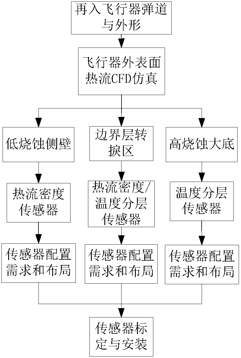
[0013] figure 1 It is a flow chart of the aerothermal measurement of the blunt body reentry vehicle of the present invention. Such as figure 1 As shown, the specific steps of the aerothermal measurement method suitable for blunt body reentry vehicles are as follows:

[0014] Step 1. According to the shape of the blunt body re-entry vehicle and the re-entry trajectory, the simulation analysis of the aerodynamic thermal load on the surface of the re-entry vehicle is carried out.

[0015] The aerodynamic thermal load can provide a reference for the scheme design of the aerodynamic thermal measurement system.

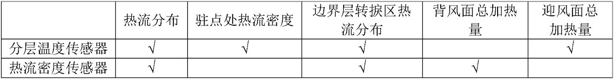
[0016] Step 2. Select the sensor and determine the measuring range according to the size and distribution of the pneumatic heating heat flow.

[0017] According to engineering experience, compared with the blunt body re-entering the out...


PUM


Abstract

The invention provides an aerodynamic heat measuring method suitable for a blunt body reentry vehicle. The aerodynamic heat measuring method is used for measuring of surface heat flow distribution ofthe side walls, the large bottom, the stagnation point area and the boundary layer transition area of the blunt body reentry vehicle and measuring of total heating capacity of the windward side and the leeward side. The aerodynamic heat measuring method comprises the following steps that according to the appearance and a reentry trajectory of the blunt body reentry vehicle, simulation analysis onaerodynamic heat load on the surface of the blunt body reentry vehicle is conducted; according to the sizes and distribution of aerodynamic heating heat flows, sensor selecting and measuring range determining are conducted; according to the aerodynamic heat measuring task requirement of the blunt body reentry vehicle, configuration demand analysis of sensors is conducted; sensor layout design is conducted; and sensor calibration and mounting are conducted. According to the aerodynamic heat measuring method, the real reentry heat flow load can be obtained, particularly, real-time data of transition of the boundary layer on the surface of the vehicle can be provided, and guiding significance is achieved on a current calculating analysis model and the ground test technical scheme.

Description

technical field [0001] The invention relates to aircraft aerodynamic thermal measurement technology, in particular to an aerodynamic thermal measurement method for a blunt body reentry aircraft, belonging to the technical field of aircraft aerodynamic measurement. Background technique [0002] Accurately grasping the aerodynamic heating characteristics of the blunt body reentry vehicle is the key to the thermal protection design of the reentry vehicle, and high-precision prediction of the reentry aerodynamic heating environment is the basis and important prerequisite for the design of the thermal protection system of the blunt body reentry vehicle. The model parameters and reliability of the traditional calculation and simulation method need to be verified, while the aerothermal test capability of the ground wind tunnel is limited, and it is impossible to reproduce the high Mach number range and the thermophysical characteristics of strong convective heating in the real fligh...

Claims


Application Information

Patent Timeline
Patent Type & Authority Applications(China)
IPC IPC(8): B64F5/60G06F17/50
CPCB64F5/00G06F30/15G06F30/20G06F2119/08Y02T90/00
Inventor 左光陈冲陈鑫屈峰邓代英李宪强侯砚泽
Owner BEIJING SPACE TECH RES & TEST CENT
Why Eureka
Try Eureka