Soiling shield for wind turbine blade

Inactive Publication Date: 2015-11-12
SIEMENS AG
View PDF1 Cites 10 Cited by
  • Summary
  • Abstract
  • Description
  • Claims
  • Application Information

AI Technical Summary

Problems solved by technology

Wind turbine blade soiling is specifically a leading edge surface contamination problem characterized by impingement of foreign objects on the leading edge during blade rotation.
In the United States, blade soiling is an acute problem in particular in the Midwest.
This accretion of foreign objects on or near the leading edge of a wind turbine blade degrades blade performance, reduces annual energy production from the WTG and increases noise emitted by the WTG.
Soiling may also lead to permanent roughing of the blade leading edge.
Specifically, soiling disturbs a flow boundary layer along the blade thereby increasing kinetic energy losses in a near-wall air flow stream.
This phenomenon reduces aerodynamic efficiency throughout the blade, negatively influencing both power production and noise emissions.
Blade soiling can also generate more warranty claims due to the decreased output po

Method used


Image

  • Soiling shield for wind turbine blade
  • Soiling shield for wind turbine blade
  • Soiling shield for wind turbine blade

Examples


Embodiment Construction

[0034]Given the problems associated with wind turbine blade soiling as described above, there is a need to reduce blade soiling to improve wind turbine generator performance.

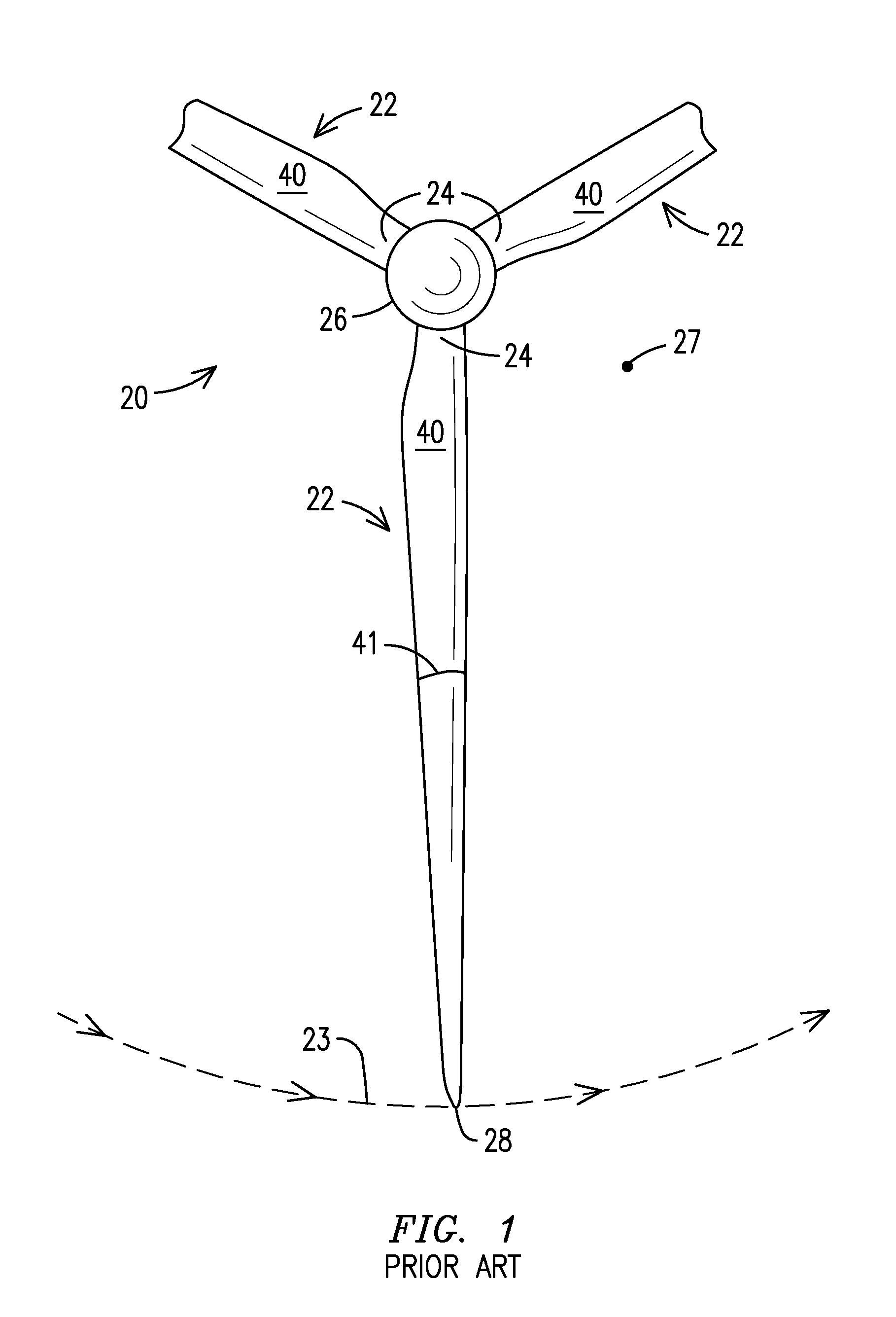
[0035]FIG. 1 illustrates a suction side (or back side) of a prior art wind turbine generator (WTG) 20 with radially-oriented blade airfoils 22, also referred to as main airfoils or simply airfoils, that rotate generally in a counter clockwise direction 23 when viewed from the suction side. A vector tip 27 represents incoming wind, i.e., the wind flowing out of the sheet. A circle circumscribed by the rotating blades is referred to as a disc of rotation or a rotor plane. Suction sides 40 of the blade airfoils 22 are seen in this FIG. 1 view. Only rotating elements are illustrated in FIG. 1; for example, the nacelle and WTG tower are not shown.

[0036]Each blade airfoil 22 extends radially from an inboard end or root end 24 to a tip end 28. The root end 24, attached to a hub 26, is relatively thick to withstand flap...


PUM

PropertyMeasurementUnit
Lengthaaaaaaaaaa
Lengthaaaaaaaaaa
Lengthaaaaaaaaaa

Abstract

A soiling shield (80) affixed to a blade airfoil (22) of a wind turbine generator (20). The soiling shield (80) includes a portion extending along and spaced apart from a pressure side surface (88) of the blade airfoil (22). The soiling shield (80) is positioned not to impede an air flow stream (98) flowing to a stagnation point (130) on the pressure side surface (88) during operation of the wind turbine generator (20) at or below rated power.

Description

FIELD OF THE INVENTION[0001]This invention relates generally to the field of wind turbine generators, and more specifically to an apparatus for reducing the accretion of foreign objects on a wind turbine blade.BACKGROUND OF THE INVENTION[0002]As is known in the art, wind kinetic energy is converted to electrical energy with a wind turbine generator (WTG). The wind turbine generator comprises rotor blades for converting wind energy to rotational energy for driving a shaft connected to a gearbox. The gearbox converts low speed rotation to high speed rotation as required for driving a generator that generates electricity. Certain WTGs lack the gearbox and instead the generator is driven directly from the shaft. The wind turbine generator also includes various control components (for example to change a blade pitch), a structural support, such as a tower, and a rotor yawing system for orienting the rotor plane perpendicular to the oncoming wind.[0003]The WTG converts wind energy to rota...

Claims


Application Information

Patent Timeline
IPC IPC(8): F03D1/06F03D1/00F03D11/00
CPCF03D1/0641Y10T29/49339F03D1/001F03D11/00F03D1/0633F03D1/0675F05B2240/301F03D80/00F03D13/10Y02E10/72
Inventor ZAMORA RODRIGUEZ, ALONSO O.
Owner SIEMENS AG
Why Eureka
Try Eureka