Unmanned aerial vehicle icing protection device

A protection device and unmanned aerial vehicle technology, applied in the field of aircraft, can solve the problems of affecting the overall performance of the engine thermal performance of the aircraft, increase energy consumption, etc., and achieve good icing protection effect, reduce energy consumption, and good effect

Inactive Publication Date: 2018-05-04
CHENGDU AIRCRAFT INDUSTRY GROUP
View PDF9 Cites 12 Cited by
  • Summary
  • Abstract
  • Description
  • Claims
  • Application Information

AI Technical Summary

Problems solved by technology

However, through the conventional electric heating method, the engine needs to provide deicing power, which will affect the thermal performance of the engine and the overall performance of the aircraft, and also increase energy consumption.

Method used


Image

  • Unmanned aerial vehicle icing protection device
  • Unmanned aerial vehicle icing protection device
  • Unmanned aerial vehicle icing protection device

Examples


Embodiment 1

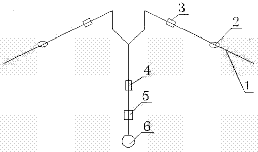
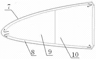
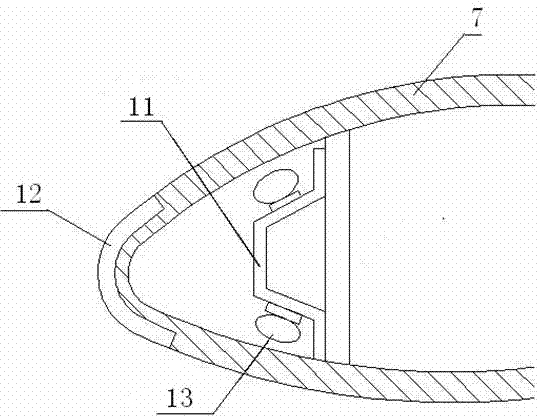
[0027] Such as Figures 1 to 3 Shown, a kind of unmanned aerial vehicle icing protection device comprises wing 1, heat conduction device and heating device, and the outer wall of described wing 1 is covered with skin 7, and the inside of described wing is formed with anti-icing cavity 2 , the anti-icing cavity 2 includes an A cavity 9 and a B cavity 10, the A cavity 9 and the B cavity 10 form an anti-icing channel with the skin 7, and the A cavity 9 and the B cavity 10 communicate through the anti-icing channel 8 , the heat conduction device includes an engine compressor 6, a flow limiter 5, a one-way valve 4 and an anti-icing valve 3, the anti-icing valve 3 is arranged on the wing 1, and one end of the anti-icing valve 3 passes through a pipeline in turn It is connected with the one-way valve 4, the flow limiter 5 and the engine compressor 6, and the other end communicates with the chamber A. The heating device includes an icing sensor 13, an electric heating layer 12 and a p...

Embodiment 2

[0030] Such as Figures 1 to 3 Shown, a kind of unmanned aerial vehicle icing protection device comprises wing 1, heat conduction device and heating device, and the outer wall of described wing 1 is covered with skin 7, and the inside of described wing is formed with anti-icing cavity 2 , the anti-icing cavity 2 includes an A cavity 9 and a B cavity 10, the A cavity 9 and the B cavity 10 form an anti-icing channel with the skin 7, and the A cavity 9 and the B cavity 10 communicate through the anti-icing channel 8 , the heat conduction device includes an engine compressor 6, a flow limiter 5, a one-way valve 4 and an anti-icing valve 3, the anti-icing valve 3 is arranged on the wing 1, and one end of the anti-icing valve 3 passes through a pipeline in turn It is connected with the one-way valve 4, the flow limiter 5 and the engine compressor 6, and the other end communicates with the chamber A. The heating device includes an icing sensor 13, an electric heating layer 12 and a p...

Embodiment 3

[0037] Such as Figures 1 to 3 Shown, a kind of unmanned aerial vehicle icing protection device comprises wing 1, heat conduction device and heating device, and the outer wall of described wing 1 is covered with skin 7, and the inside of described wing is formed with anti-icing cavity 2 , the anti-icing cavity 2 includes an A cavity 9 and a B cavity 10, the A cavity 9 and the B cavity 10 form an anti-icing channel with the skin 7, and the A cavity 9 and the B cavity 10 communicate through the anti-icing channel 8 , the heat conduction device includes an engine compressor 6, a flow limiter 5, a one-way valve 4 and an anti-icing valve 3, the anti-icing valve 3 is arranged on the wing 1, and one end of the anti-icing valve 3 passes through a pipeline in turn It is connected with the one-way valve 4, the flow limiter 5 and the engine compressor 6, and the other end communicates with the chamber A. The heating device includes an icing sensor 13, an electric heating layer 12 and a p...


PUM


Abstract

The invention relates to an unmanned aerial vehicle icing protection device comprising wings, a heat conduction device and a heating device. The outer walls of the wings are covered with skins, and anti-icing cavities are formed in the wings. The heat conduction device comprises an engine compressor, a flow limiter, a one-way valve and anti-icing valves, and the anti-icing valves are arranged on the wings. The heating device comprises icing sensors, electric heating layers and pulse devices which are connected sequentially. According to the unmanned aerial vehicle icing protection device, heatof an engine and the electric heating and pulse devices are mixed for deicing, the advantages of the heat of the engine and the electric heating and pulse devices are combined, a good icing protection effect is formed, namely it is guaranteed that no ice layer exists nearby important parts such as stagnation points at the front edges of the wings, damage of icing to the aerodynamic shape of a vehicle is also reduced, and the power consumption of the vehicle is reduced.

Description

technical field [0001] The invention belongs to the technical field of aircraft, and in particular relates to an icing protection device for an unmanned aerial vehicle. Background technique [0002] The icing protection system is one of the important systems related to the flight safety of the aircraft. At present, the hot air anti-icing system and the electric thermal anti-icing system are commonly used. The protected aircraft surface includes the leading edge of the wing (tail), helicopter blades, engine Intake leading edge, etc. These two system solutions are relatively mature in technology and have been widely used in military and civilian aircraft. UAVs generally undertake reconnaissance or attack missions. In the mission profile, when they encounter icing weather environments, they need icing protection. System to ensure flight safety, the wing is the main lifting surface, but also the main icing protection surface. If a conventional hot gas anti-icing system or an e...

Claims


Application Information

Patent Timeline
Patent Type & Authority Applications(China)
IPC IPC(8): B64D15/04B64D15/12B64D15/16B64D15/20
CPCB64D15/04B64D15/12B64D15/163B64D15/20
Inventor 刘磊艾素宵何泳熊莉
Owner CHENGDU AIRCRAFT INDUSTRY GROUP
Why Eureka
Try Eureka