

Aircraft handler
- Summary
- Abstract
- Description
- Claims
- Application Information
AI Technical Summary
Benefits of technology
Problems solved by technology
Method used
Image

Examples
Embodiment Construction
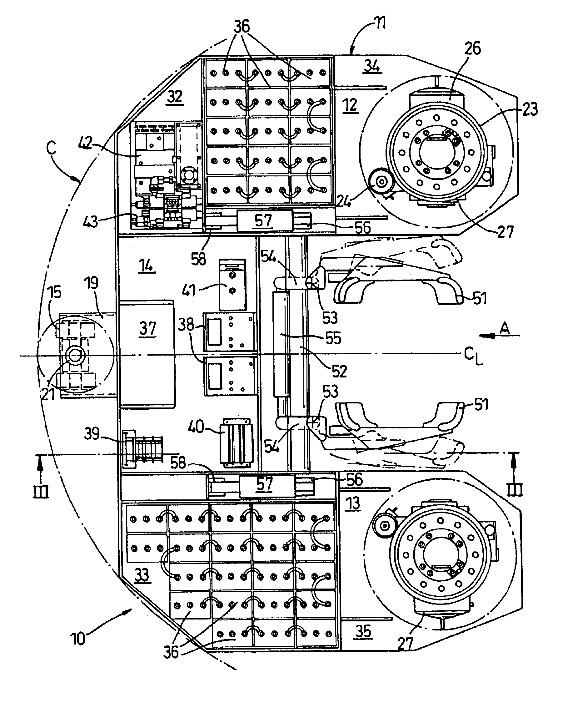
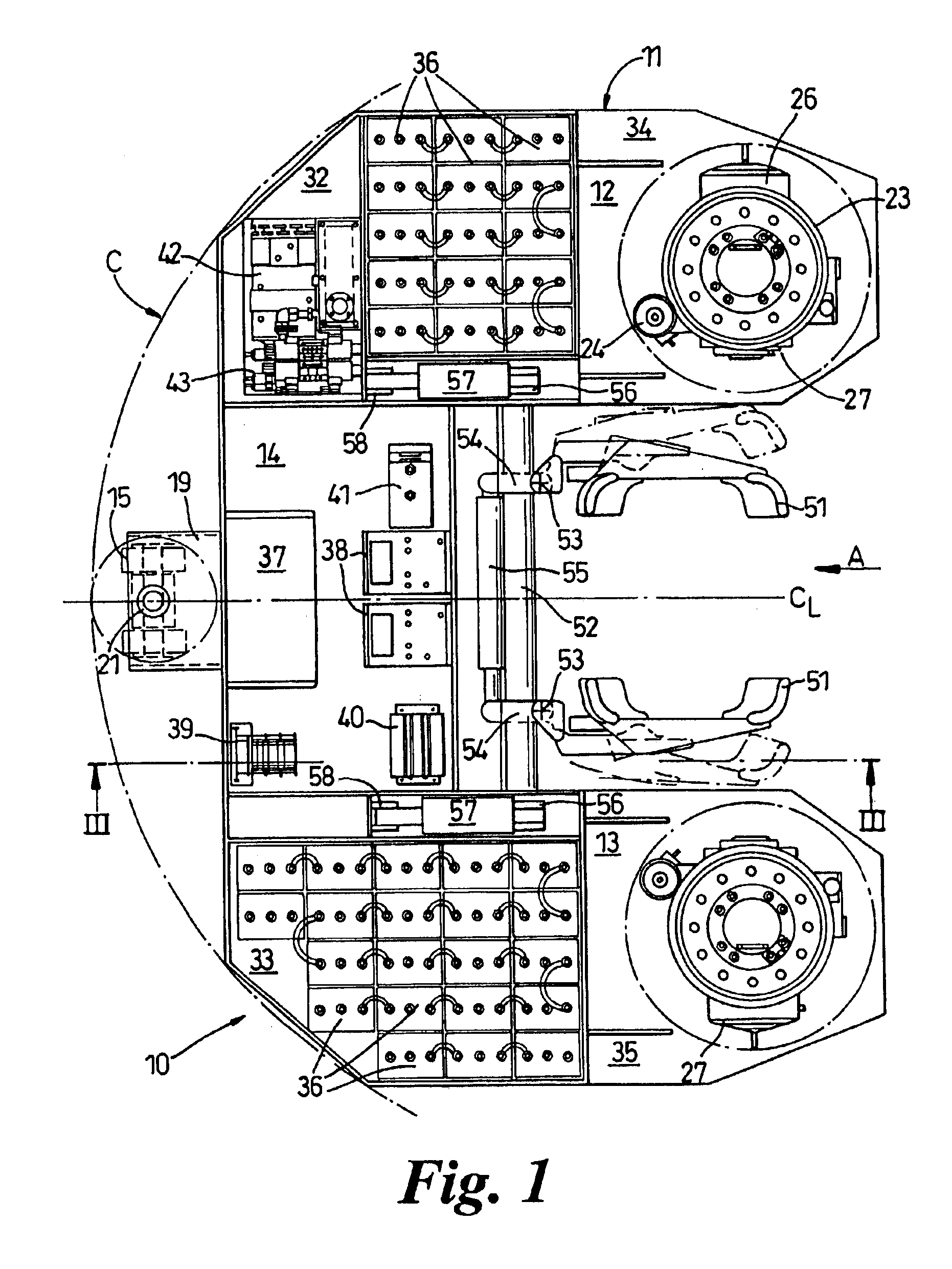
[0022]With reference to the drawings, there is shown an aircraft handler which is for use in co-operation with the front undercarriage of an aircraft, and in particular for use with a helicopter nose wheel. The handler is self-propelled as will be described later.
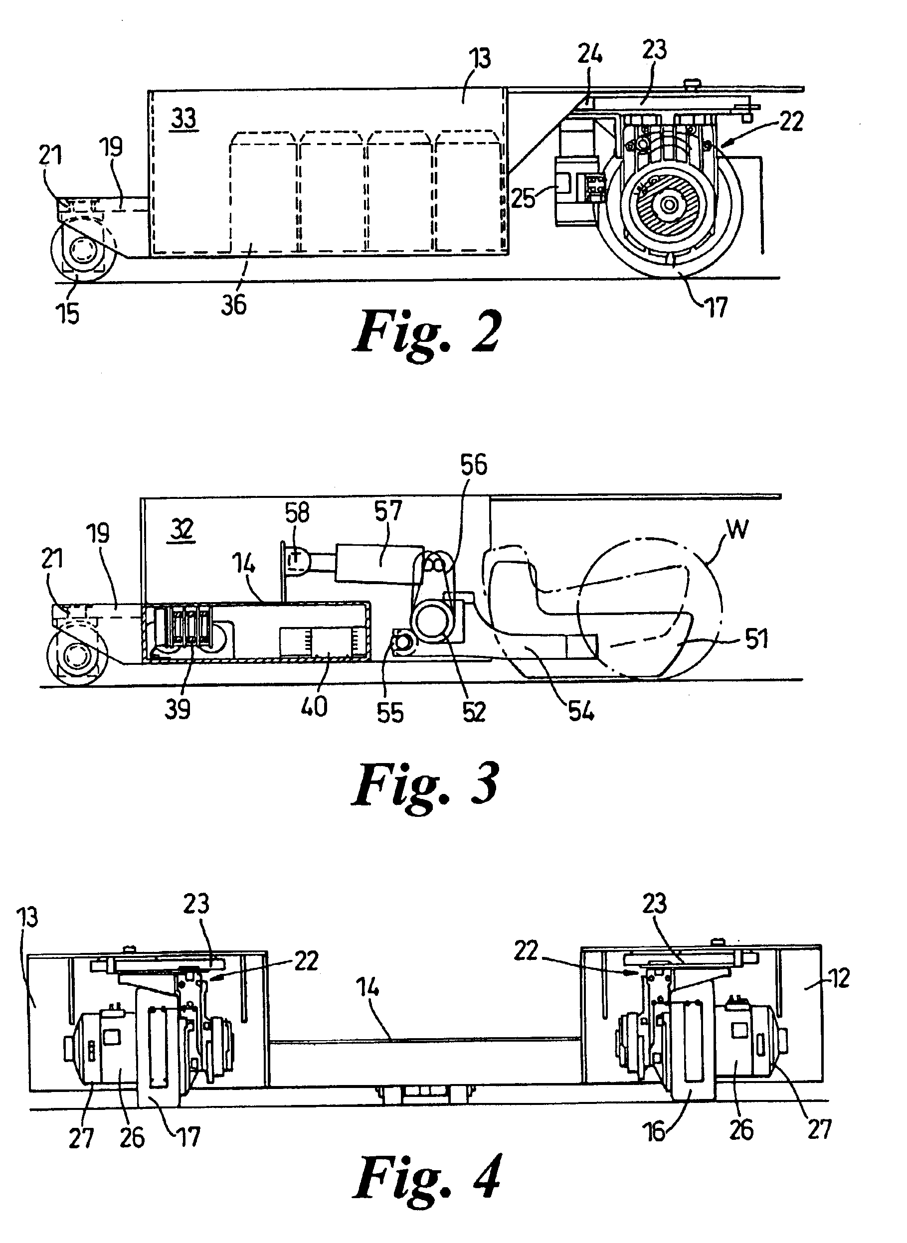
[0023]The handler 10 has a body or chassis 11 which in plan view is substantially “U” shaped or horseshoe shaped having two arms 12&13 linked by a bridge 14. The body 10 stands on wheels 15,16&17, the wheels 16&17 being located at the end portions 34,35 of each respective arm 12&13, and wheel(s) 15 being secured to the front of the bridge 14 at its centre line CL. The bridge 14 is lower than the arms 12&13 having a height of about 200 mm as compared with the height of the arms which is about 460 mm. The fronts 12&13 of the arms are inclined or chamfered so that the inclined portions and the wheels 15 substantially lie on a pitch circle C struck from the intersection of the centre line CL and the axis of rotation of lifting ...
PUM
 Abstract
Description
Claims
Application Information