Rocker recliner mechanism

a technology of recliner and mechanism, which is applied in the direction of chairs, vehicle components, vehicle arrangements, etc., can solve the problems of complex mechanisms, difficult manufacturing and assembly of complex mechanisms, and unstable reclining chairs that include rocker arrangements. achieve the effect of economic manufacturing and ease of operation

Inactive Publication Date: 2005-09-20
UFI IP LLC +1
View PDF58 Cites 35 Cited by
  • Summary
  • Abstract
  • Description
  • Claims
  • Application Information

AI Technical Summary

Benefits of technology

[0004]A recliner mechanism for a rocking chair provides stability while reclined at an increased pitch, may be economically manufactured, and provides ease of operation by the user, by having a rocker locking linkage to lock the chair against rocking motion when the ottoman of the chair is extended. The rocker locking linkage preferably includes a drive link slidingly connected to a drive element for driving a locking element to lock the chair against rocking motion. The main drive link may also be slidingly connected to a rocker cam assembly, and may drive two locking elements. The mechanism preferably includes an ottoman linkage having a guide link slidingly connected to the ottoman linkage. The mechanism also preferably includes a locking element to lock the chair against forward rocking motion by orienting pivoting locking members in a substantially aligned arrangement.

Problems solved by technology

However, a reclining chair that includes a rocker arrangement may become unstable when the ottoman is elevated and extended, unless a locking mechanism is provided to prevent rocking movement of the chair when the ottoman is in the extended position.
Such mechanisms, which are typically handle-operated can be complex and include many pans in their linkages.
A complex mechanism may be more difficult to manufacture and assemble, and may also require the user to apply an undesirable amount of force to the handle to operate the mechanism.

Method used


Image

  • Rocker recliner mechanism
  • Rocker recliner mechanism
  • Rocker recliner mechanism

Examples


Embodiment Construction

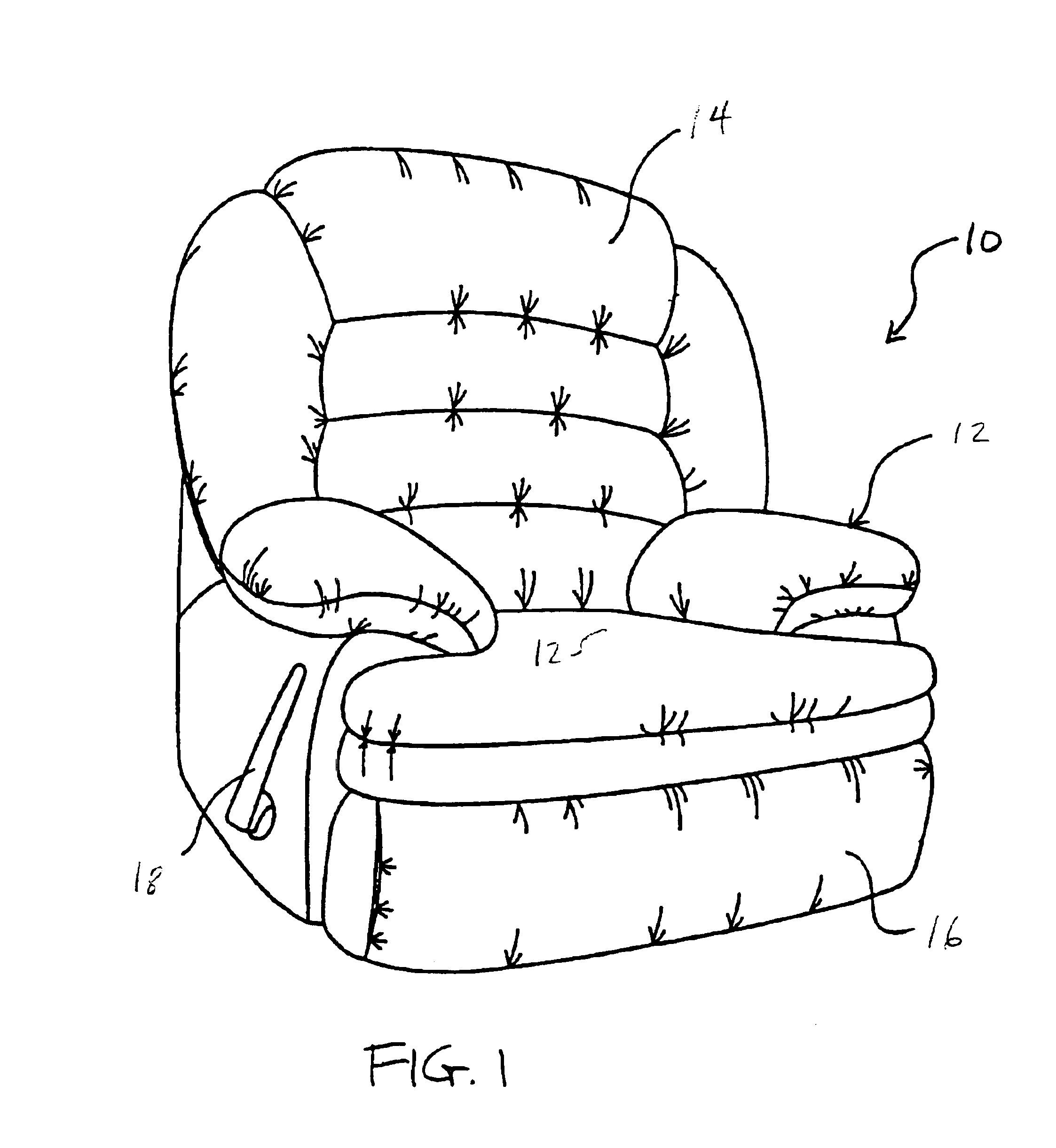
[0019]The chair 10, as seen in FIG. 1, may be upholstered in fabric, leather, or other suitable material and includes an upholstered seat and arm frame unit 12, an upholstered back 14 and an upholstered ottoman 16. Only the primary member of the ottoman 16 shows in FIG. 1, the secondary member being stored out of view behind the primary member of ottoman 16 in the upright position of the chair. (It should be noted that ottomans are sometimes also known as legrests or footrests). In the illustrated embodiment, extension of the ottoman 16 is operated by handle 18, at least for initiation of the extension, as will be described presently.

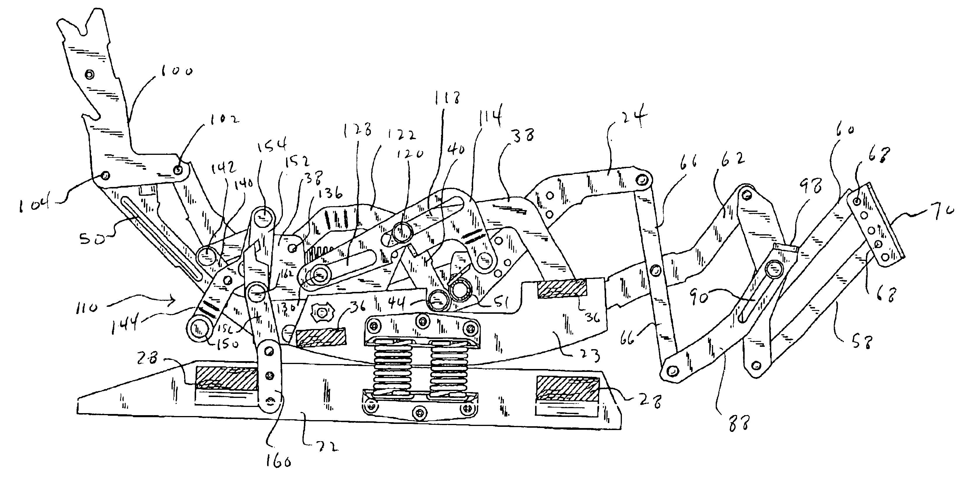
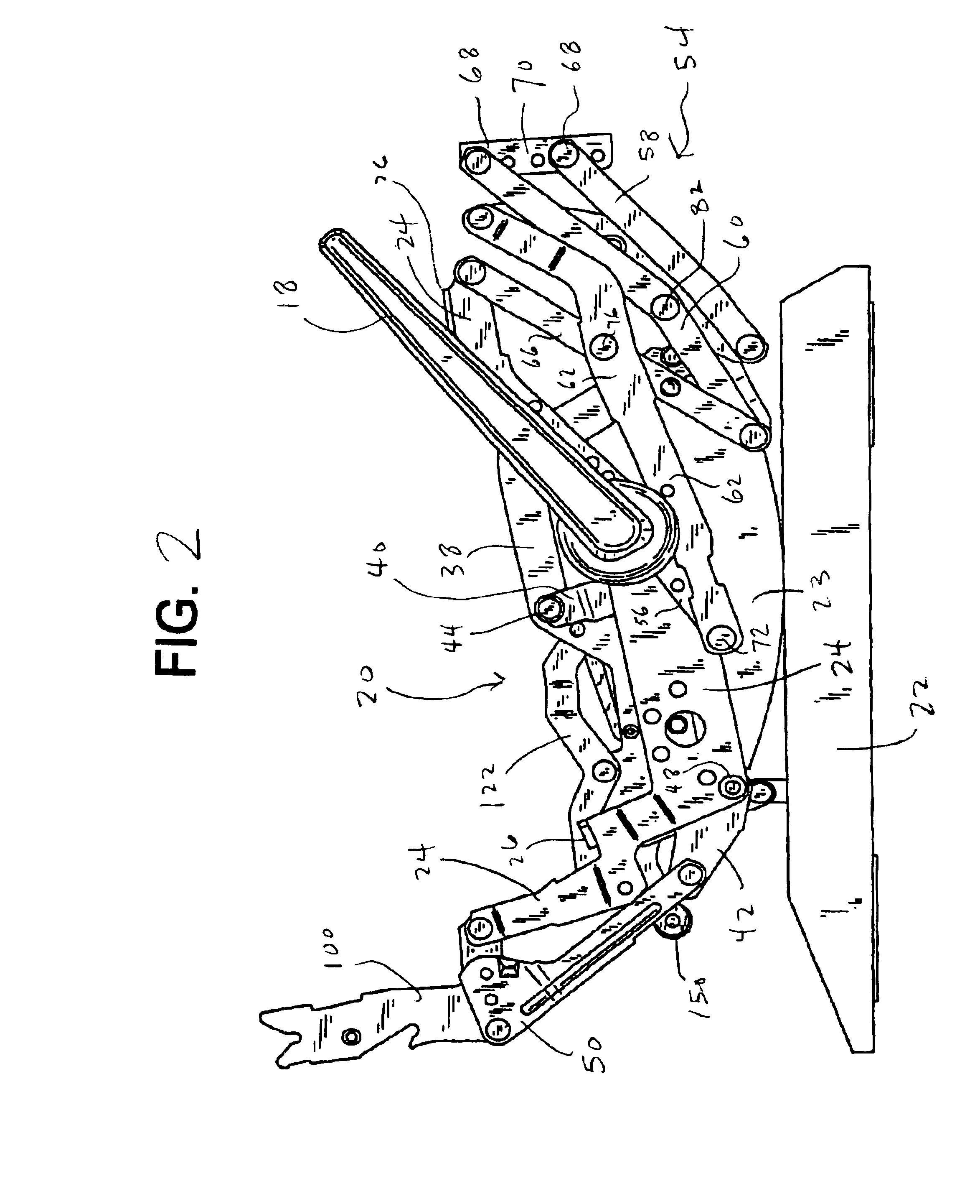
[0020]A right-side rocking reclining mechanism 20 is shown in FIG. 2, viewed from a position rightward of the mechanism itself. A base member 22 is constructed of wood or other suitable material, and rests on a floor or other supporting surface. A rocker cam 23 rests on the base member 22, and has an arc-shaped lower surface to permit forward and rearwa...


PUM


Abstract

A mechanism for a rocker recliner chair is caused to have enhanced comfort and stability, to have enhanced ease of operation, and to require fewer parts for manufacture. The mechanism includes a rocker locking linkage arranged to include a drive link slidingly connected to a drive element, to drive a locking member for locking of the chair against rocking when the ottoman of the chair is extended. The drive link of the rocker locking linkage may also be arranged to be slidingly connected to a rocker cam assembly of the chair. The rocker locking linkage preferably includes a pair of locking links moveable to a substantially aligned orientation to lock a chair against forward rocking movement. The chair preferably includes an ottoman linkage including a slotted guide member.

Description

BACKGROUND OF THE INVENTION[0001]The present invention relates to a rocker reclining chair and a mechanism for such a chair, and especially to a rocker reclining chair and mechanism which provides a greater degree of comfort to a user, provides enhanced stability, particularly when the ottoman of the chair is extended, provides enhanced ease of operation, and which may require a reduced number of parts to manufacture.[0002]Reclining chairs may be more comfortable if the chair's ottoman (also known as a leg rest or footrest) can be elevated and extended while the back of the chair is tilted rearward to allow the user to comfortably recline with his or her feet raised. A higher degree of elevation (or pitch) of the ottoman may provide a higher degree of comfort. However, a reclining chair that includes a rocker arrangement may become unstable when the ottoman is elevated and extended, unless a locking mechanism is provided to prevent rocking movement of the chair when the ottoman is i...

Claims


Application Information

Patent Timeline
Patent Type & Authority Patents(United States)
IPC IPC(8): A47C3/027A47C3/03A47C3/02
CPCA47C3/027A47C3/03Y10S297/07
Inventor MAY, TEDDY J
Owner UFI IP LLC
Why Eureka
Try Eureka