Self-locking rotatable electrical coupling
a technology of rotatable electrical coupling and self-locking, which is applied in the direction of current collectors, coupling device connections, electrical apparatus, etc., can solve the problems of reducing the effective length of the power cord, limiting the useful range of the tool coupled to the power cord, and causing the cord to twist or become knotted during us
- Summary
- Abstract
- Description
- Claims
- Application Information
AI Technical Summary
Problems solved by technology
Method used
Image

Examples
Embodiment Construction
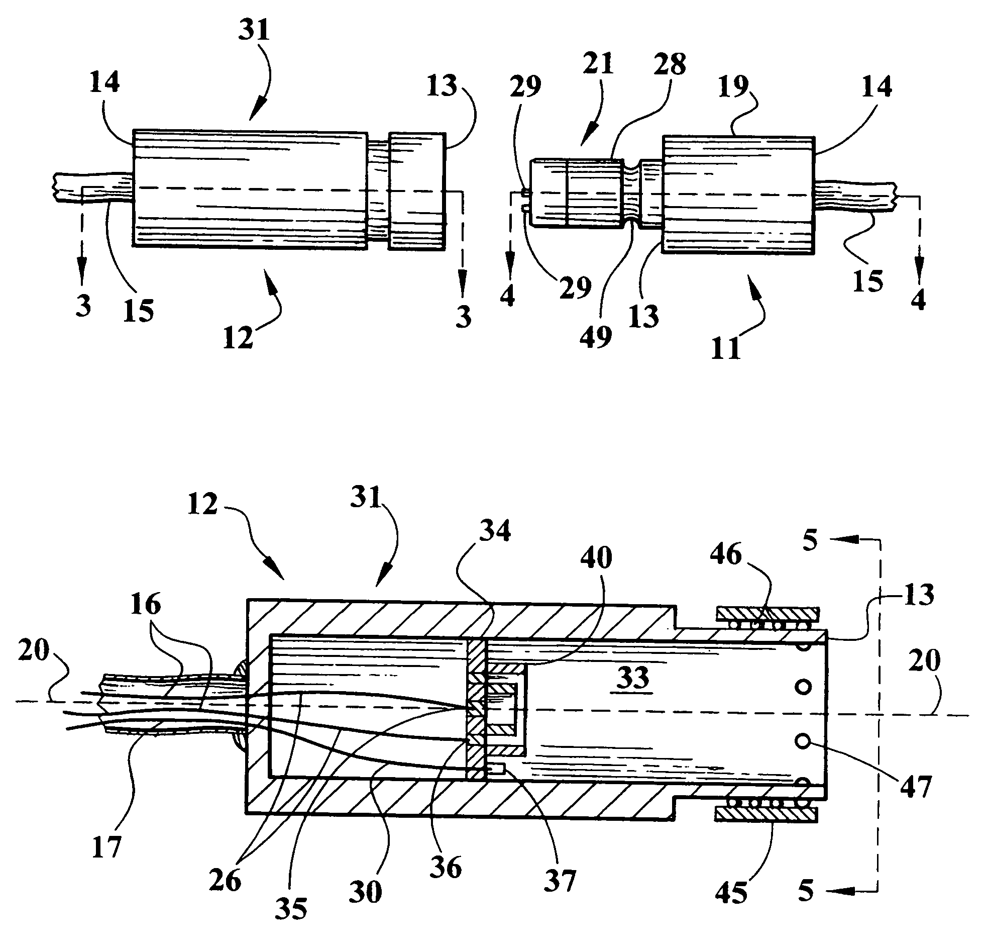
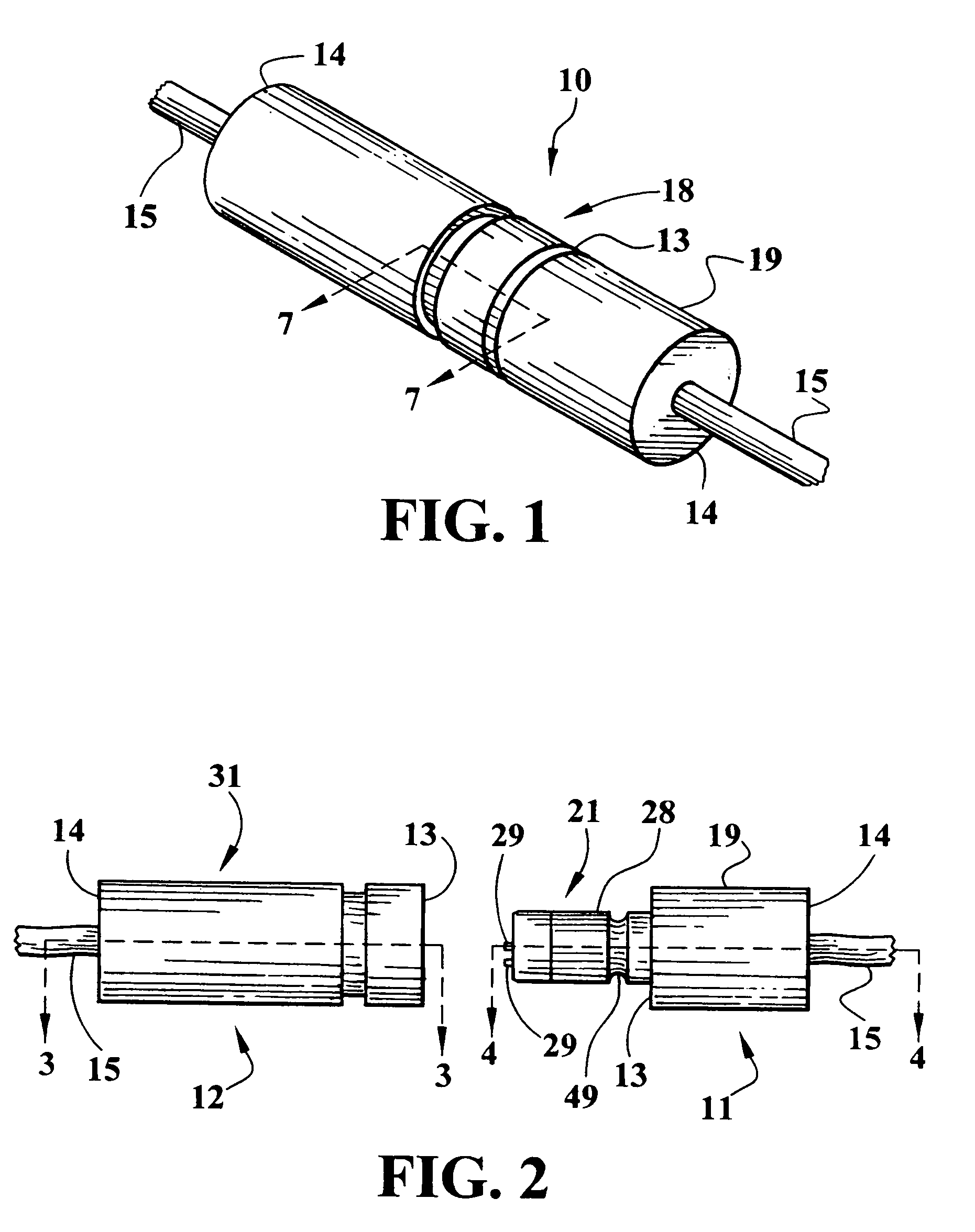
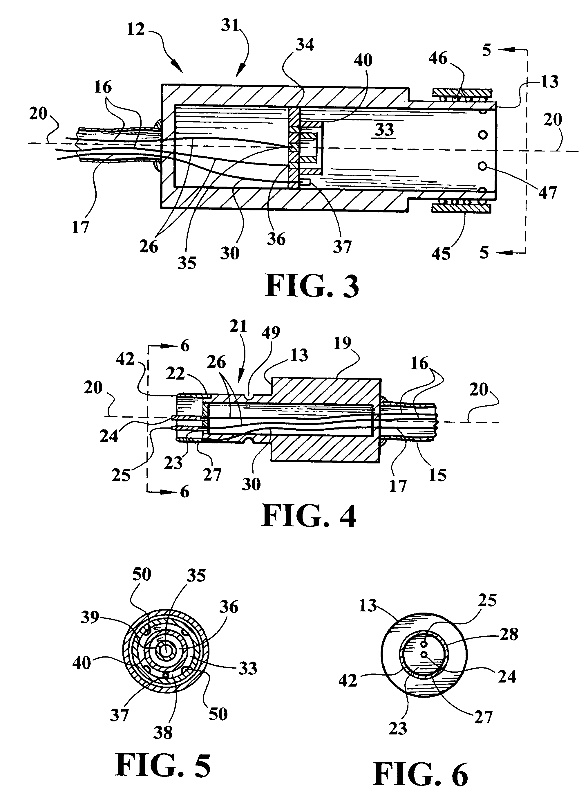
[0043]Referring now to FIGS. 1–8, an embodiment of the coupling device 10 of the present invention is shown comprised of male and female components 11 and 12, respectively, each having a mating front extremity 13 and rearwardly opposed infeed extremity 14. Electric cables 15 that contain two polarized power conductor lines 16 and a third, ground wire line 17 enter said rear infeed extremities 14. A spring-activated locking mechanism 18 interactively connects said components at their mating extremities 13, as shown in FIG. 1.
[0044]Said male component is comprised of a base structure 19 fabricated of an electrically non-conductive material such as a moldable plastic. The exemplified base structure is shown having a circular cylindrical shape elongated upon center axis 20. Alternative shapes may, however, be employed. A cylindrical coupling post 21 is emergent from said base structure at mating extremity 13, preferably as a continuous integral extension of base structure 19. Post 21 te...
PUM
 Abstract
Description
Claims
Application Information
 - Generate Ideas
- Intellectual Property
- Life Sciences
- Materials
- Tech Scout
- Unparalleled Data Quality
- Higher Quality Content
- 60% Fewer Hallucinations
Browse by: Latest US Patents, China's latest patents, Technical Efficacy Thesaurus, Application Domain, Technology Topic, Popular Technical Reports.
© 2025 PatSnap. All rights reserved.Legal|Privacy policy|Modern Slavery Act Transparency Statement|Sitemap|About US| Contact US: help@patsnap.com