Method for flange bonding

Active Publication Date: 2005-09-20
NIKE INC
View PDF27 Cites 62 Cited by
  • Summary
  • Abstract
  • Description
  • Claims
  • Application Information

AI Technical Summary

Benefits of technology

[0011]Following positioning of the first and second components in an abutting relationship, the flanges may be bonded together. The bond may encircle the axially aligned conduits and be space

Problems solved by technology

More complex fluid systems, however, require that the individual component

Method used


Image

  • Method for flange bonding
  • Method for flange bonding
  • Method for flange bonding

Examples


Embodiment Construction

[0034]Introduction

[0035]Referring to the figures and the following discussion, wherein like numerals indicate like elements, a method for flange bonding in accordance with the present invention is disclosed. The method for flange bonding is particularly suited for use with footwear fluid systems and other types of athletic equipment. The concepts presented in the following discussion and figures, however, may also have applications in the medical, automotive, and aerospace industries, for example. Accordingly, the present invention is intended to encompass flange bonding techniques that are suitable for a wide range of products in diverse areas of manufacture.

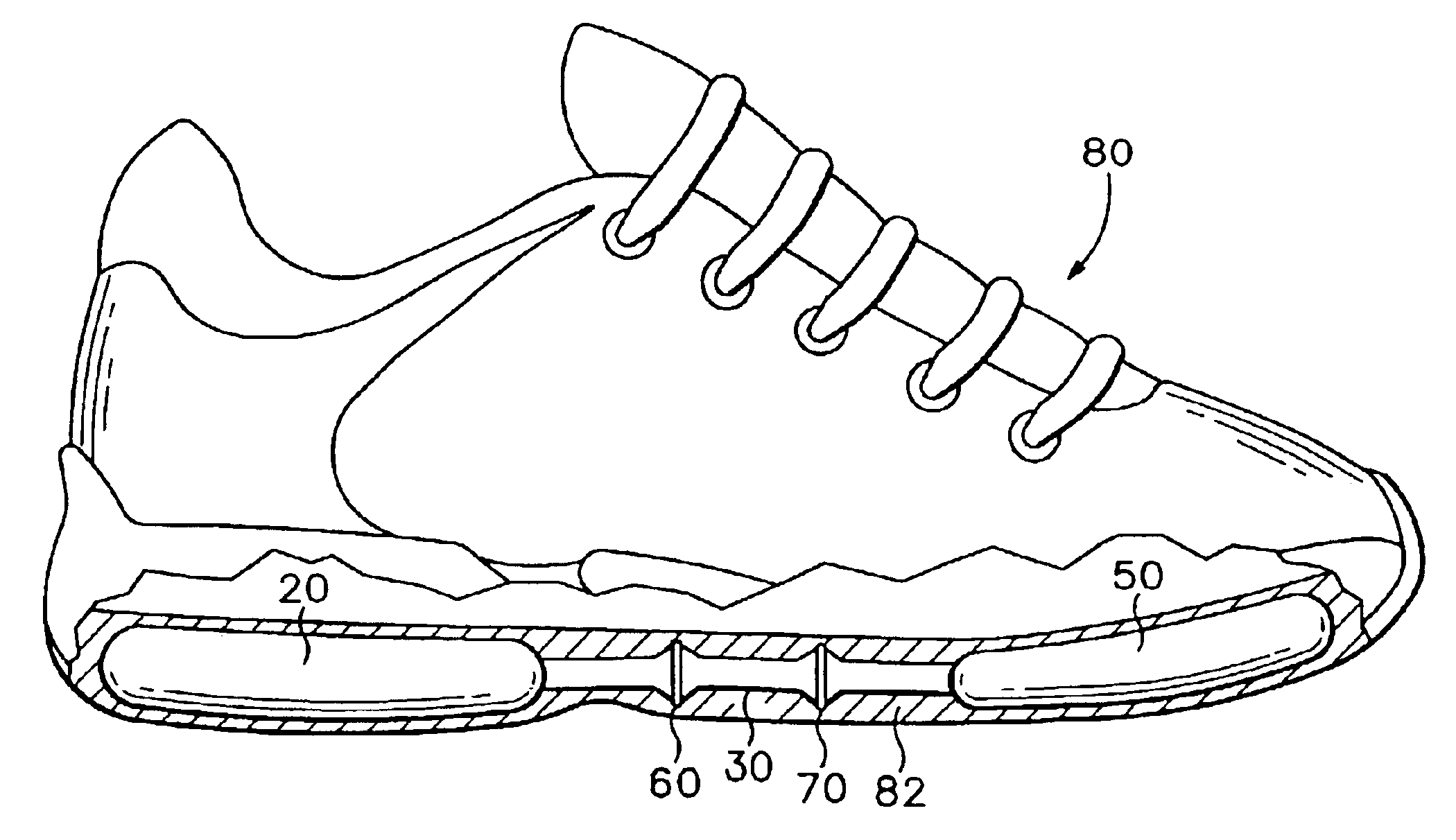
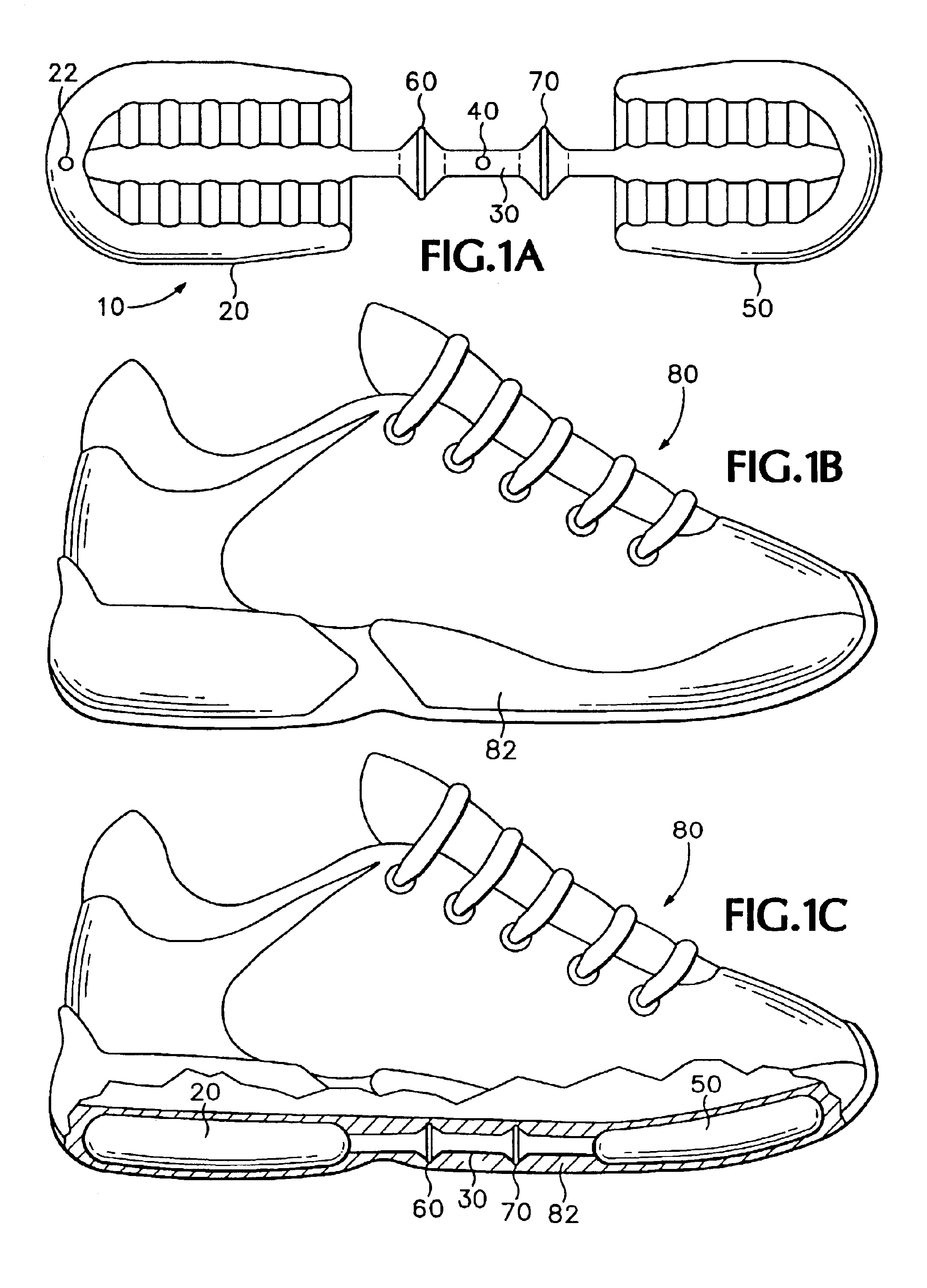
[0036]An exemplar fluid system 10 is depicted in FIG. 1A and includes a pump chamber 20, a conduit 30, a valve 40, and a pressure chamber 50. Fluid system 10 also includes a first flange bond 60 that joins pump chamber 20 with conduit 30, and fluid system 10 includes a second flange bond 70 that joins an opposite end of conduit...


PUM

PropertyMeasurementUnit
Perimeteraaaaaaaaaa
Bondaaaaaaaaaa

Abstract

The invention is a method for joining two components of a fluid system. The method involves forming a first flange on a first fluid component and placing the first flange in an abutting relationship with a second flange that is formed on a second fluid component. The abutting relationship may be such that conduit portions of the fluid components are axially aligned. The flanges may then be bonded together such that the bond encircles the conduits and prevents fluid from entering or exiting the system from the bond. A bond of this type also places the first and second components in fluid communication. The fluid system may be incorporated into a sole structure of an article of footwear.

Description

BACKGROUND OF THE INVENTION[0001]1. Field of the Invention[0002]The present invention relates to fluid systems. The invention concerns, more particularly, a method for joining two components of a fluid system. The fluid system utilizes polymer components and finds particular use in footwear sole structures.[0003]2. Description of Background Art[0004]The primary elements of conventional footwear are an upper and a sole structure. Athletic footwear sole structures are generally formed of three layers, customarily referred to as an insole, a midsole, and an outsole. The insole is a thin, cushioning member located adjacent to the foot that improves footwear comfort. The midsole, typically formed of polyurethane or ethylvinylacetate foam, imparts both ground reaction force attenuation and energy absorption. The outsole provides a wear-resistant, ground-contacting surface.[0005]Midsoles often incorporate fluid-filled bladders to enhance the ground reaction force attenuation and energy abs...

Claims


Application Information

Patent Timeline
IPC IPC(8): A43B13/18A43B13/20B29C57/00B29C57/04
CPCA43B13/203B29C57/04
Inventor DOJAN, FREDHAZENBERG, K. PETER
Owner NIKE INC
Why Eureka
Try Eureka