Electromechanical transducer

Inactive Publication Date: 2005-09-20
EHNDRESS KHAUZER GMBKH KO KG
View PDF10 Cites 220 Cited by
  • Summary
  • Abstract
  • Description
  • Claims
  • Application Information

AI Technical Summary

Benefits of technology

[0022]One advantage of the invention is that the terminal lugs are a component of the flexible printed circuit board. In other words, they are not individual, loose components that entail additional expenses but instead are merely specially shaped portions of the printed circuit board that is present anyway.
[0023]The terminal lugs of the flexible printed circuit board are especially well suited to production by machine. For instance, all the terminal lugs can be provided simultaneously with adhesive by machine and then equipped by machine with the piezoelectric elements. In the same assembly operation, further electronic components to be provided on the flexible printed circuit board are mounted in a single operation. Thus the manufacture of the electromechanical transducers of the invention can be done very quickly, quasi-fully automatically, and hence quite economically.

Problems solved by technology

Producing such a stack is very labor-intensive.
This is very expensive, especially given the high numbers of items typically required.

Method used


Image

  • Electromechanical transducer
  • Electromechanical transducer
  • Electromechanical transducer

Examples


Embodiment Construction

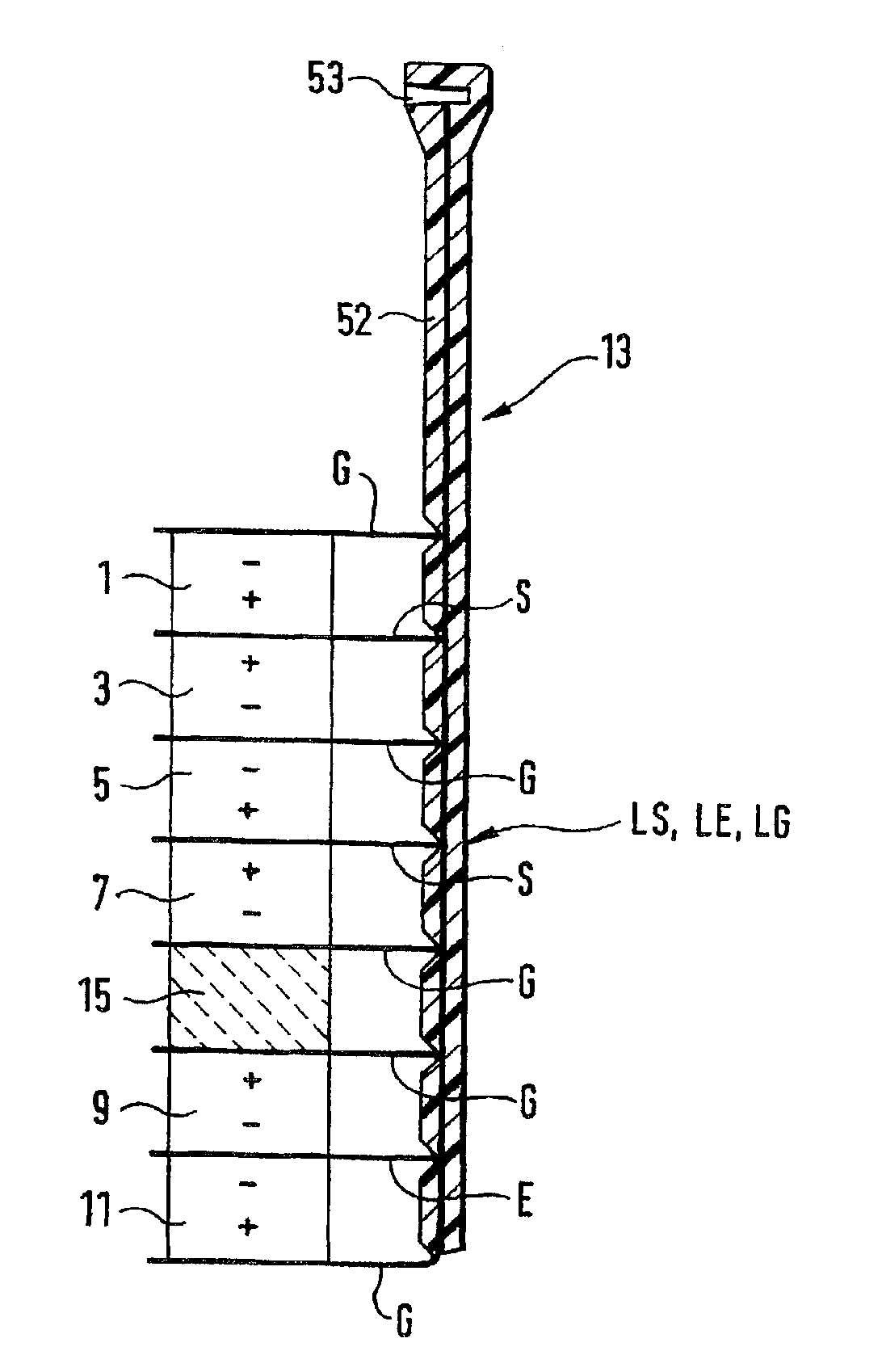
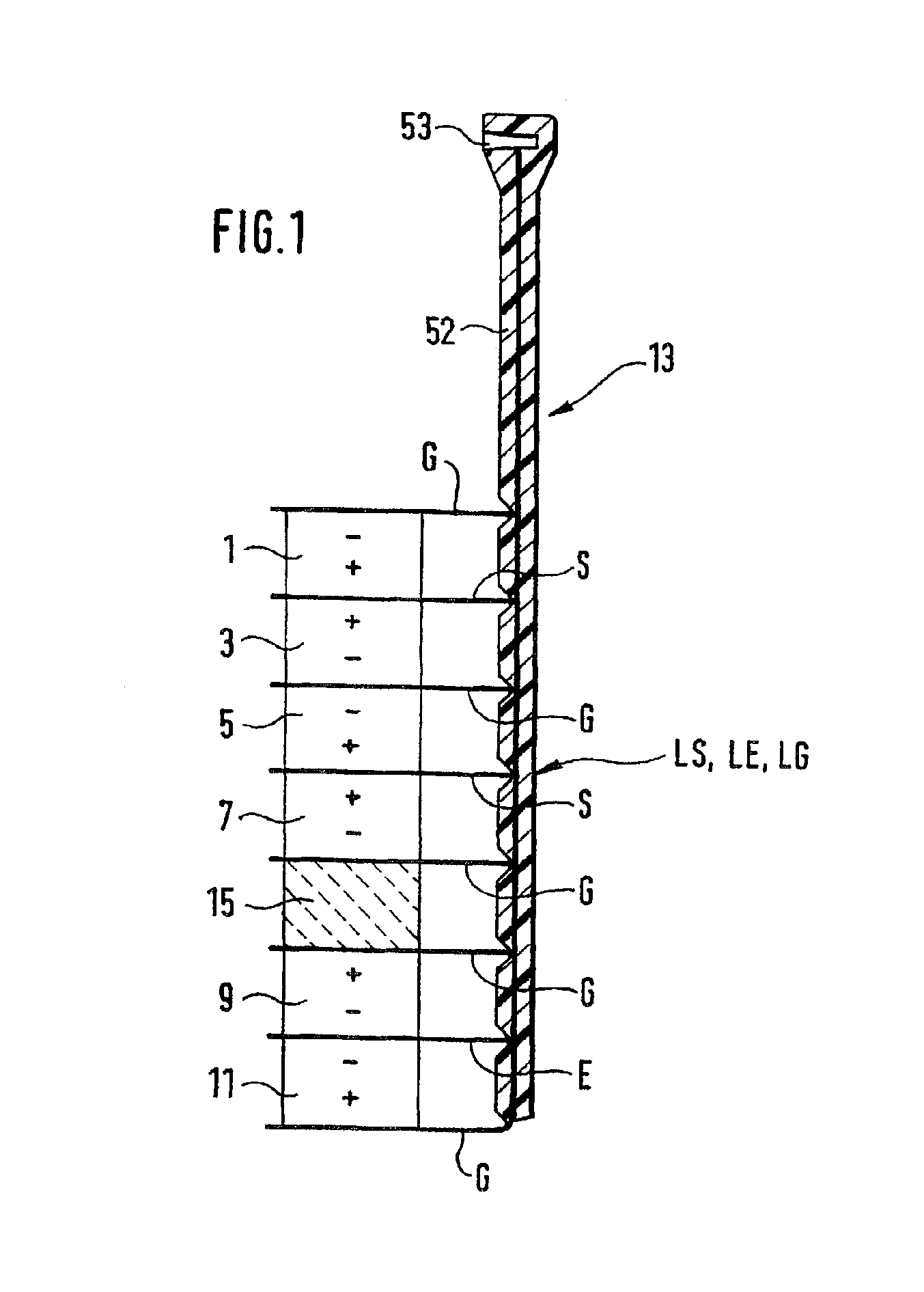
[0032]FIG. 1 shows an electromechanical transducer embodied according to the invention. It includes piezoelectric elements 1, 3, 5, 7, 9, 11 disposed in a stack. Between the piezoelectric elements 1, 3, 5, 7, 9, 11, there is one contact electrode S, E or G each above the topmost piezoelectric element 1 and below the bottommost piezoelectric element 11. The piezoelectric elements 1, 3, 5, 7, 9, 11 are connected electrically via the contact electrodes S, E, G to lines extending in a flexible printed circuit board 13; in the selected exemplary embodiment, these lines are a transmission signal line LS, a reception signal line LE, and a ground line LG. In the selected exemplary embodiment, the contact electrodes S are connected to the transmission signal line LS, the contact electrodes E are connected to the reception signal line LE, and the contact electrodes G are connected to the ground line LG.

[0033]The order of the piezoelectric elements and their electrical mode of connection to co...


PUM


Abstract

The invention relates to an electromechanical transducer that is easy and inexpensive to produce. The inventive transducer comprises stacked piezoelectric elements between which contact electrodes (G, S, E) are interposed via which the piezoelectric elements are electrically connected. The contact electrodes (G, S, E) are configured as planar terminal lugs that are connected to the outside from a flexible printed board.

Description

FIELD OF THE INVENTION[0001]The invention relates to an electromechanical transducer, with piezoelectric elements disposed in a stack, between which contact electrodes are disposed by way of which the piezoelectric elements are electrically connected.BACKGROUND OF THE INVENTION[0002]Such electromechanical transducers are used in measurement and regulating technology, for instance. As an example, devices for ascertaining and / or monitoring a predetermined fill level in a container that have a mechanical oscillation structure, mounted at the level of the predetermined fill level, that is excited into oscillation by an electromechanical transducer are available on the market. One example of such a device is described in German Patent Disclosure DE-A 41 18 793. The oscillations of the mechanical oscillation structure are picked up and converted into electrical signals, which are accessible for further processing and / or evaluation. From the electrical signals, a frequency and / or an amplit...

Claims


Application Information

Patent Timeline
IPC IPC(8): H01L41/00H01L41/047H04R17/00H05K1/18H04R31/00
CPCH04R17/005H01L41/0833H01L41/0471H01L41/0472H01L41/0475H05K1/189H10N30/871H10N30/872H10N30/875H10N30/503H10N30/101
Inventor BIRGEL, DIETMAR
Owner EHNDRESS KHAUZER GMBKH KO KG
Why Eureka
Try Eureka