

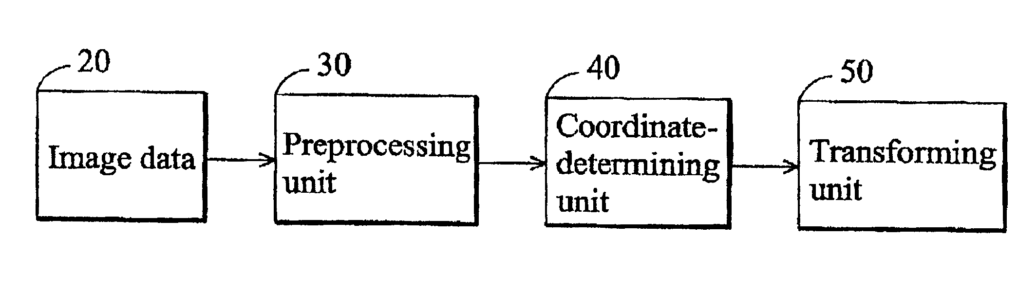
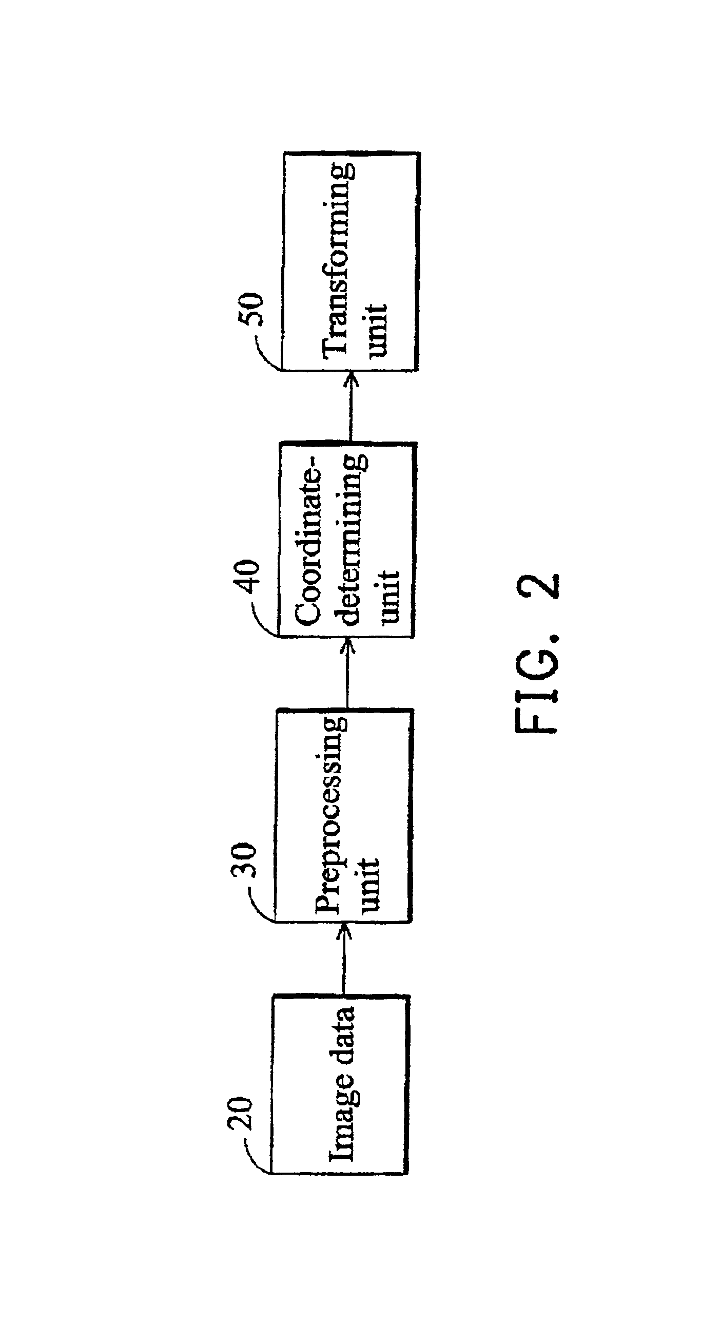
Method of correcting an image with perspective distortion and producing an artificial image with perspective distortion
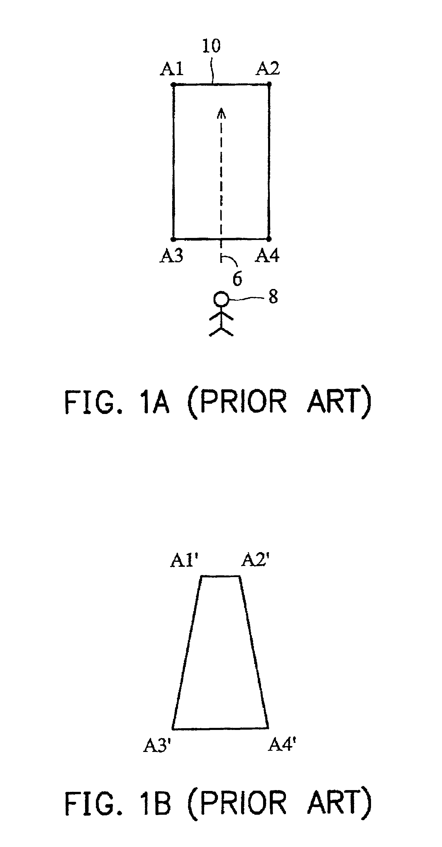
a technology of perspective distortion and image, applied in the field of image processing technology, can solve the problems of inconvenient user experience and perception distortion
- Summary
- Abstract
- Description
- Claims
- Application Information
AI Technical Summary
Benefits of technology
Problems solved by technology
Method used
Image

Examples
first example
[0061]The central line in the first example is denoted by C1l. The four corners of the distorted object image are denoted by q, r, C12l and C11l, respectively, where the coordinates of C12l and C11l are undetermined. In addition, the two corners s and r and another two points p and q constitute four corners of a rectangle, where p=(0,0), q=(W,0), r=(W,H) and s=(0,H). The central line C1l is determined by the intersection Z7 of extensions of the two sides {overscore (qC11l)} and {overscore (rC12l)}. Thus, the central line C1l is a line perpendicular to the side {overscore (C11lC12l)} passing through the point Z7, where the intersection of the central line C1l and the side {overscore (C11lC12l)} is E7.
[0062]The coordinates of the corners q, r, C12l and C11l are determined by the known distorted side (D=LEFT), the central line C1l and the distortion ratio F. As described above, the coordinates of the corners q and r are (W,0) and (W,H), respectively. The coordinates of the corners C11l...
second example
[0068]The central line in the first example is denoted by C2l and located above the distorted object image. The four corners of the distorted object image are denoted by p, C21l, r and C22l, respectively, where the coordinates of the two corners C21l and C22l are undetermined. The central line C2l is determined by the intersection Z8 of extensions of the two sides {overscore (C21lp)} and {overscore (rC22l)}. Thus, the central line C2l is a line perpendicular to an extension of the side {overscore (C22lp)} passing through the point Z8, where the intersection of the central line C2l and the extension of the side {overscore (C22lp)} is E8. In addition, the length of the line segment {overscore (E8Z8)} is denoted by l2l.
[0069]With respect to the corner C22l, its x coordinate is the same as the x coordinate of the point p (that is, 0) and its y coordinate is calculated by:
C22l,y=y2l+(H−y2l)×F (19)
[0070]where y2l is a negative number and represents the y coordinate of the central line C2...
third example
[0073]The central line in the first example is denoted by C3l and located below the distorted object image. The four corners of the distorted object image are denoted by q, C32l, s and C31l respectively, where the coordinates of the two corners C32l and C31l are undetermined. The central line C3l is determined by the intersection Z9 of extensions of the two sides {overscore (C32ls)} and {overscore (qC31l)}. Thus, the central line C3l is a line perpendicular to an extension of the side {overscore (C31ls)} passing through the point Z9, where the intersection of the central line C3l and the extension of the side {overscore (C31ls)} is E9. In addition, the length of the line segment {overscore (E9Z9)} is denoted by l3l.
[0074]With respect to the corner C31l, its x coordinate is the same as the x coordinate of the point s (that is, 0), and its y coordinate is calculated by:
C31l,y=y3l−y3l×F (21)
[0075]where y3l represents the y coordinate of the central line C3l.
[0076]With respect to the c...
PUM
 Abstract
Description
Claims
Application Information