
Torque wrench with sleeve for locking rotatable handle

a rotatable handle and torque wrench technology, which is applied in the direction of rod connections, instruments, force/torque/work measurement apparatus, etc., can solve the problems of complex machining steps, parts such as leaf springs that can fatigue and fail, and the conventional locking mechanism in the known rotatable adjustable handle can be easily rotated, improved locking mechanism, and reduced failures.

Inactive Publication Date: 2005-09-27
PRECISION INSTR
View PDF12 Cites 50 Cited by
  • Summary
  • Abstract
  • Description
  • Claims
  • Application Information

AI Technical Summary

Benefits of technology

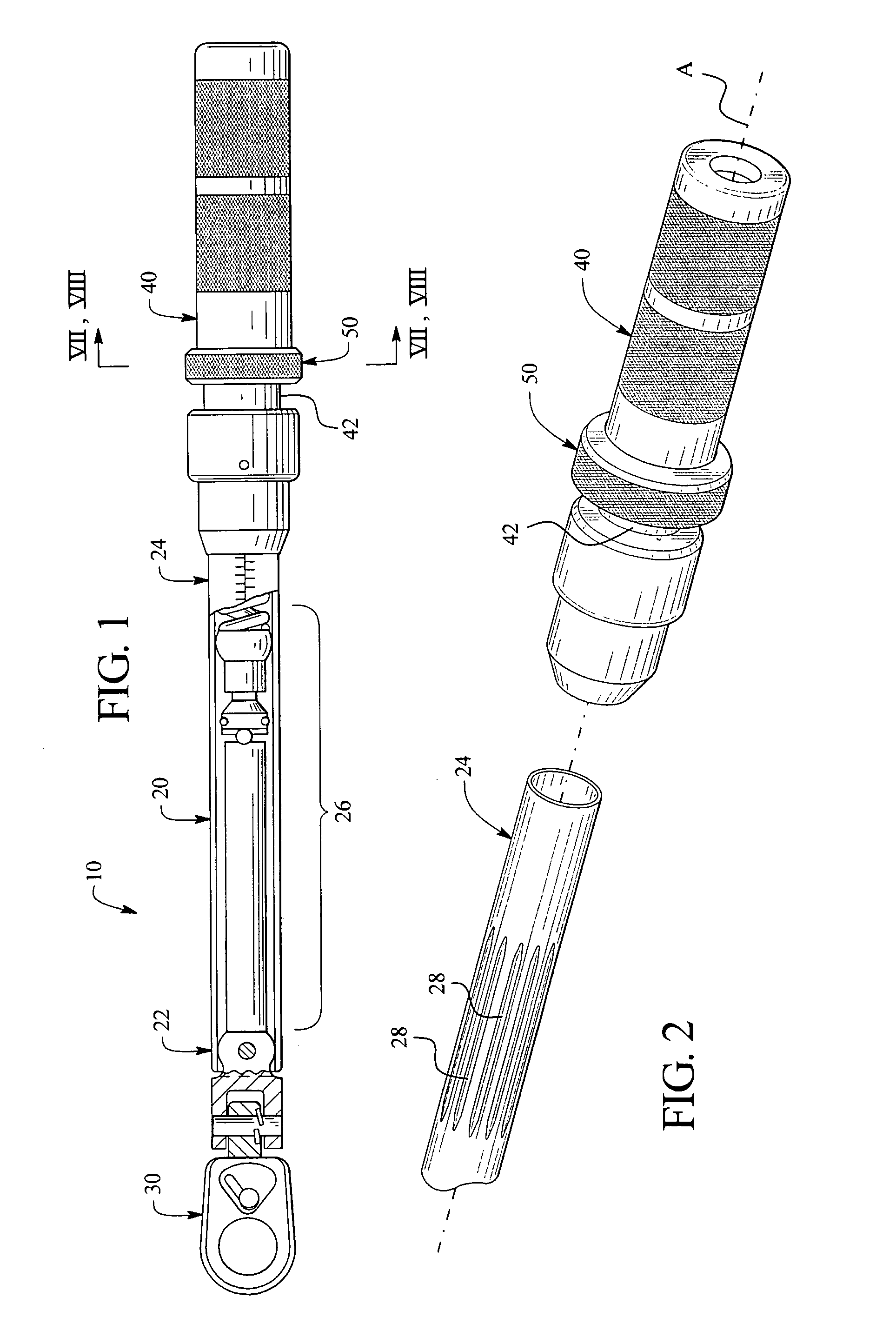
[0010]An advantage of the present invention is that it provides a torque wrench having an improved locking mechanism in the handle. The improved locking mechanism avoids a need for complicated machining steps during manufacture, and reduces parts that can fail.
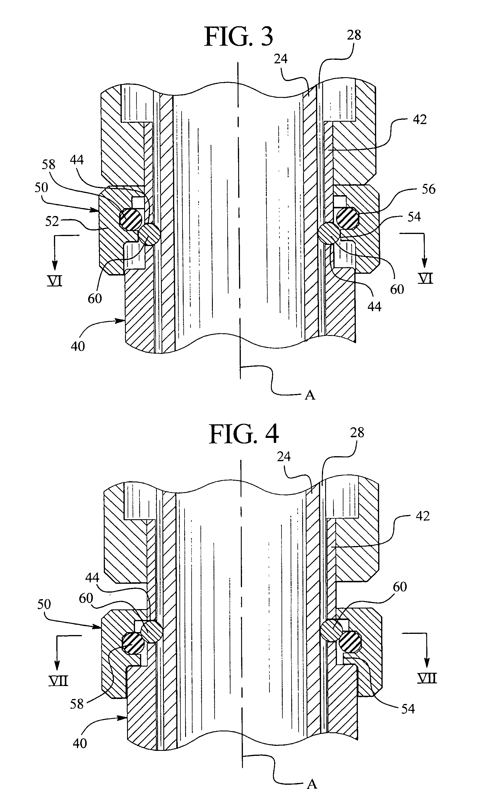
[0011]In an embodiment, another advantage of the present invention is that the locking sleeve includes an elastomeric member, such as an O-ring, which avoids a need for a metal spring.
[0012]Yet another advantage of the present invention is that it provides a locking sleeve that can be retained indefinitely in the unlocked position. In an embodiment, the locking sleeve advantageously “clicks” into the unlocked position in which it is held by a slight bias. A related advantage is that in the unlocked position, the handle can be easily rotated to incrementally adjust the torque setting.
[0013]In an embodiment, a further advantage of the present invention is that it provides a locking ball that can seat in at least one detent or recess while allowing for facile locking and unlocking by slidably moving the locking sleeve that can be biased toward the unlocked position. A related advantage is that when the locking sleeve is in the unlocked position, the locking ball can incrementally “click” over the detents during handle rotation.

Problems solved by technology

Problems exist with conventional locking mechanisms in known rotatably adjustable handles mounted to these hand tools.
For example, conventional handle locking mechanisms have required complicated machining steps during manufacture, and the parts such as the leaf spring can fatigue and fail.

Method used


Image

  • Torque wrench with sleeve for locking rotatable handle
  • Torque wrench with sleeve for locking rotatable handle
  • Torque wrench with sleeve for locking rotatable handle

Examples


Embodiment Construction

[0022]While the invention will be described in connection with the preferred embodiment, it will be understood that there is no intent to limit the scope of the invention to this embodiment. On the contrary, it is intended that the claims will cover all alternatives, modifications and equivalents as may be included within the spirit and scope of the invention.

[0023]Torque wrenches have been developed to attach fasteners of many types to meet varying specifications. Such hand tools can include micrometer adjustable click wrenches and the like, such as that described in U.S. Pat. No. 5,503,042 to Larson et al., herein incorporated by reference in its entirety. The structure for useful torque wrenches is generally disclosed in U.S. Pat. No. 5,503,042, and in the present invention is embodied in an improved locking mechanism in a rotatable handle.

[0024]Now referring to the drawings, wherein like numerals designate like components, FIG. 1 illustrates a torque wrench 10 which generally in...


PUM


Abstract

A torque wrench is provided having body and a handle that is rotatably mounted to the body for adjusting the torque setting, and an axially movable sleeve operable to selectively lock the handle. The sleeve includes a rigid member and an elastomeric member, such as an O-ring, and the sleeve is configured to act against a locking ball held in a bore of the handle. The sleeve is selectively movable between two positions: (a) a locked position wherein the rigid member firmly retains the locking ball seated in one of several detents in the body, thereby preventing rotation of the handle; and (b) an unlocked position wherein the elastomeric member biases the locking ball inwardly, deflecting when the locking ball unseats from the detent to permit handle rotation. When the sleeve is in the unlocked position, the locking ball can incrementally “click” over the detents during handle rotation.

Description

FIELD OF THE INVENTION[0001]This invention generally pertains to torque wrenches and more particularly to torque wrenches having a rotatable handle for adjusting a torque setting.BACKGROUND OF THE INVENTION[0002]Adjustable torque wrenches are generally known. One common style of torque wrench has a rotatable handle that is operable to adjust a torque setting. Some conventional handles can have a slidable locking sleeve including an interior coil spring biasing the sleeve toward the locked position. Another conventional locking sleeve is rotatable and includes an interior cam surface acting on a leaf spring. Problems exist with conventional locking mechanisms in known rotatably adjustable handles mounted to these hand tools. For example, conventional handle locking mechanisms have required complicated machining steps during manufacture, and the parts such as the leaf spring can fatigue and fail.[0003]Thus, an improved locking sleeve is needed.BRIEF SUMMARY OF THE INVENTION[0004]The p...

Claims


Application Information

Patent Timeline
IPC IPC(8): B25B23/14F16B21/00B25B23/142F16B7/04
CPCB25B23/1427F16B7/042Y10T403/592Y10S403/06
Inventor LARSON, JOHN ANDREW
Owner PRECISION INSTR
Learn More