Check valve device

Active Publication Date: 2005-09-27
SMC CORP
View PDF13 Cites 9 Cited by
  • Summary
  • Abstract
  • Description
  • Claims
  • Application Information

AI Technical Summary

Benefits of technology

[0010]A general object of the present invention is to provide a check valve device which makes it possible to prevent the pressure fluid such as a liquid chemical flowing through a fluid passage from harmful effect.
[0011]According to the present invention, all constituent elements arranged in a fluid passage including an elastic member for urging a valve plug toward a seat section are formed of resin materials. Accordingly, for example, even when a liquid chemical or the like is used as pressure fluid, the check valve device can be used appropriately without any harmful influence on the component of the liquid chemical.

Problems solved by technology

For example, when the conventional check valve as described above is incorporated into a semiconductor manufacturing apparatus through which liquid chemical or the like flows, some iron rust or the like may appear, or some harmful influence may be exerted on the component of the flowing liquid chemical.

Method used


Image

  • Check valve device
  • Check valve device
  • Check valve device

Examples


Embodiment Construction

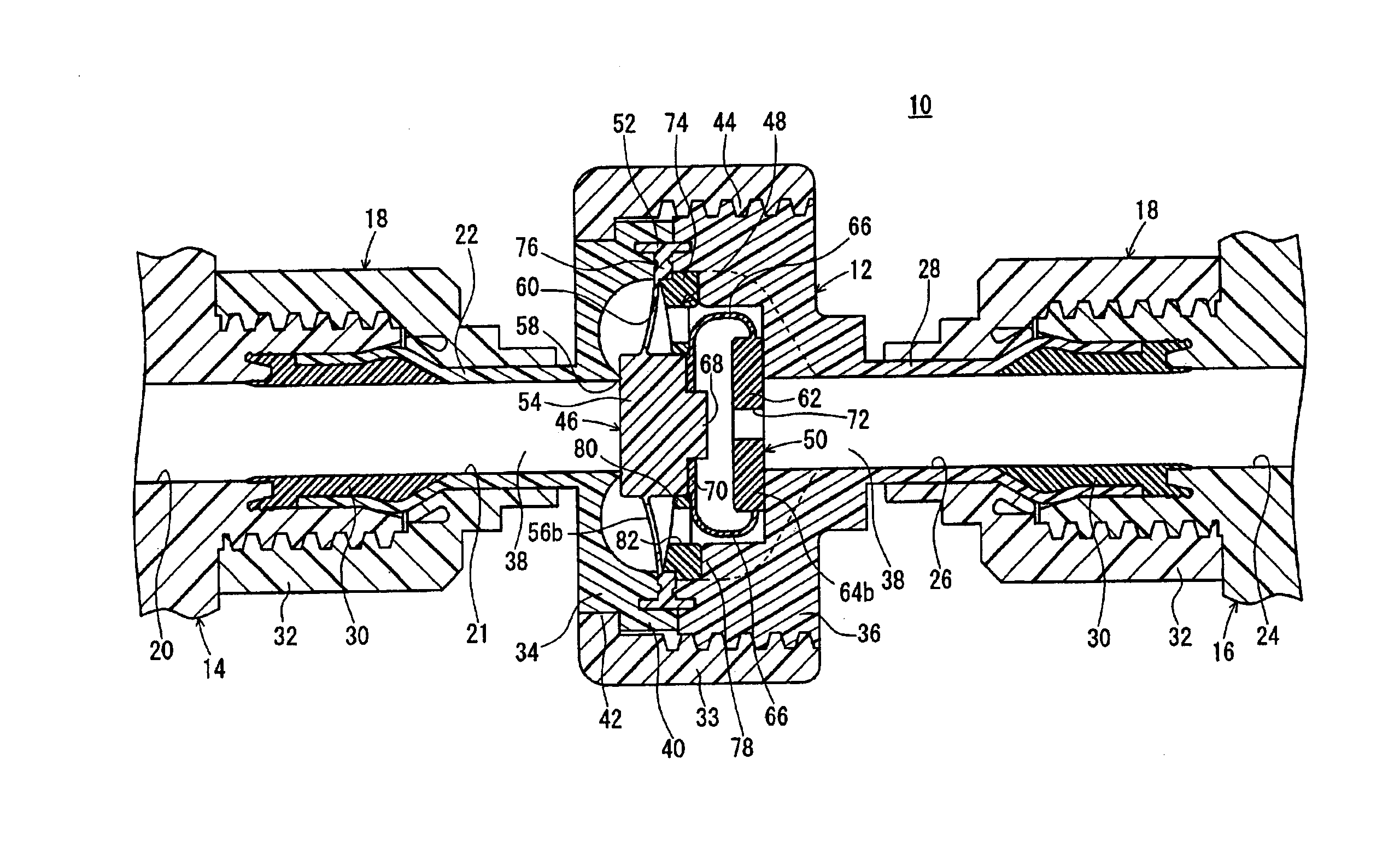
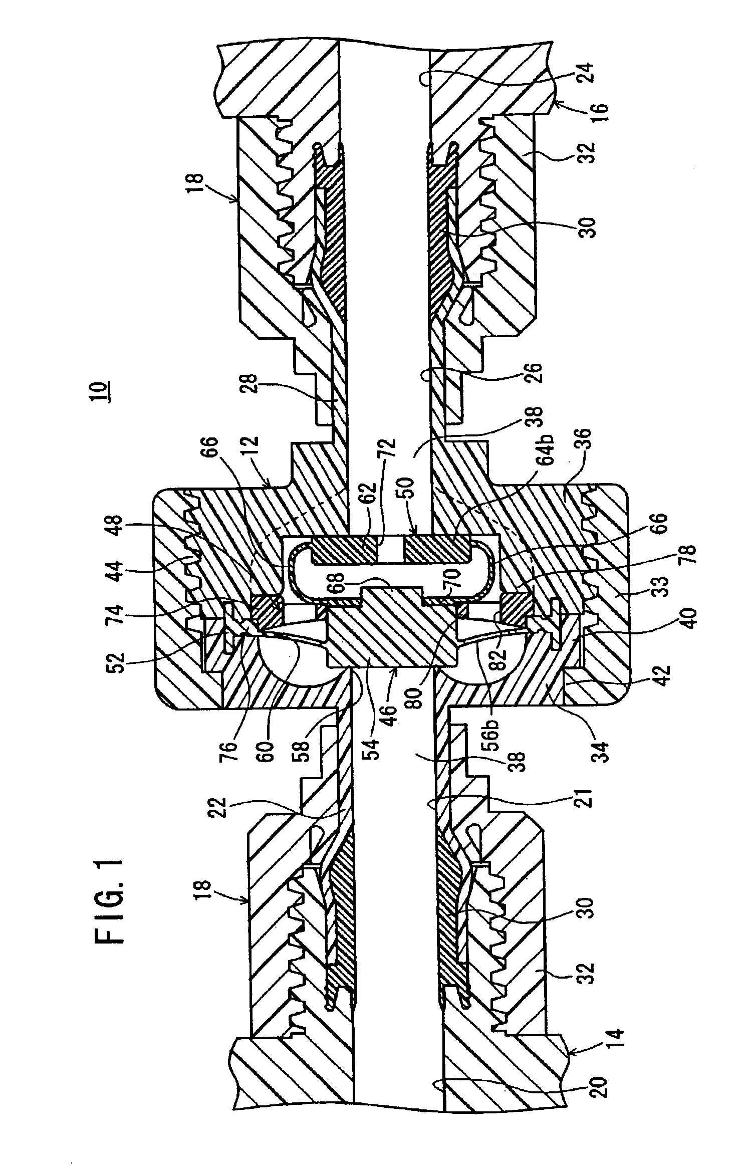
[0020]With reference to FIG. 1, reference numeral 10 indicates a check valve device according to an embodiment of the present invention.

[0021]The check valve device 10 comprises a body 12 and joint sections 18. The body 12 has a substantially disk-shaped configuration. The joint sections 18 are separated from each other by a predetermined distance on both sides of the body 12. The joint sections 18 are detachably connected to other fluid pressure-operated apparatuses 14, 16. All parts of the body 12 and the joint sections 18 are formed of resin materials.

[0022]The joint section 18 has a first port 21 communicating with a fluid passage 20 of the fluid pressure-operated apparatus 14. The joint sections 18 include a first tube section 22 which protrudes by a predetermined length from the body 12, and a second tube section 28 which is provided coaxially with the first tube section 22 on the opposite side of the body 12 and which is formed with a second port 26 for communicating with a f...


PUM


Abstract

A check valve device includes a valve section of a valve plug arranged in a fluid passage of a body, the valve plug being in a valve-opened state when separated from a seat section, and the valve plug being in a valve-closed state when seated on the seat section, and an elastic member which urges the valve section by the spring property of bent spring sections so that the valve section is seated on the seat section. The body, the valve plug, and the elastic member are formed of resin materials.

Description

BACKGROUND OF THE INVENTION[0001]1. Field of the Invention[0002]The present invention relates to a check valve device which makes it possible to flow a pressure fluid in only one direction through a fluid passage and which makes it possible to prevent the pressure fluid from flowing in the opposite direction.[0003]2. Description of the Related Art[0004]A check valve is used for flowing a pressure fluid in only one direction and preventing the pressure fluid from flowing in the opposite direction in a fluid circuit.[0005]FIG. 7 shows such a conventional check valve. The check valve 1 includes a body 2 and a cover 3 which are connected to form a substantially cylindrical shape, and a seat ring 4 interposed at the connecting portion between the body 2 and the cover 3.[0006]The check valve 1 further includes a seat section 5 of a rubber material covering the seat ring 4, a valve plug 6 which is capable of being seated on the seat section 5, a spring-receiving member 7 contacting the val...

Claims


Application Information

Patent Timeline
IPC IPC(8): F16K15/14F16K15/02
CPCF16K15/021F16K15/144Y10T137/7856Y10T137/7922Y10T137/7937
Inventor FUKANO, YOSHIHIRO
Owner SMC CORP
Why Eureka
Try Eureka