Reconstitution device and method of use

a reconstitution device and a technology of a restitution device, applied in the direction of liquid handling, packaging goods, food packaging, etc., can solve the problems of turbulence and/or frothing on the surface of fluid, and the user's concern that the reconstitution has not occurred correctly

Inactive Publication Date: 2005-09-27
TAKEDA PHARMA CO LTD
View PDF78 Cites 164 Cited by
  • Summary
  • Abstract
  • Description
  • Claims
  • Application Information

AI Technical Summary

Benefits of technology

[0006]In one embodiment, a reconstitution device is disclosed and includes a first container receiver having a first component cannula disposed therein, the first component cannula having a withdrawal port and a first transfer port formed thereon, a second container receiver having a second component cannula disposed thereon, the second component cannula having a vent port and a second transfer port formed thereon, a device body coupling the first container receiver to the second container receiver and having a transfer lumen formed therein, the transfer lumen in fluid communication with the first and second transfer ports, a selectively sealing interface secured to the device body and in fluid communication with the withdrawal port, and a venting member in communication with the vent port through a vent lumen.
[0007]In an alternate embodiment, a reconstitution device is disclosed and includes a first container receiver having a first component cannula disposed therein, the first component cannula having a withdrawal port and a first transfer port formed thereon, a second container receiver having a second component cannula disposed thereon, the second component cannula having a vent port and a second transfer port formed thereon, a device body coupling the first container receiver to the second container receiver and havin

Problems solved by technology

In addition, the liquid flowing from the spike and dropping into the solid phase container may cause turbulence and/or frothing

Method used


Image

  • Reconstitution device and method of use
  • Reconstitution device and method of use
  • Reconstitution device and method of use

Examples


Embodiment Construction

[0021]Disclosed herein is a detailed description of various embodiments of the invention. This description is not to be taken in a limiting sense, but is made merely for the purpose of illustrating the general principles of the invention. The overall organization of the present detailed description is for the purpose of convenience only and is not intended to limit the invention.

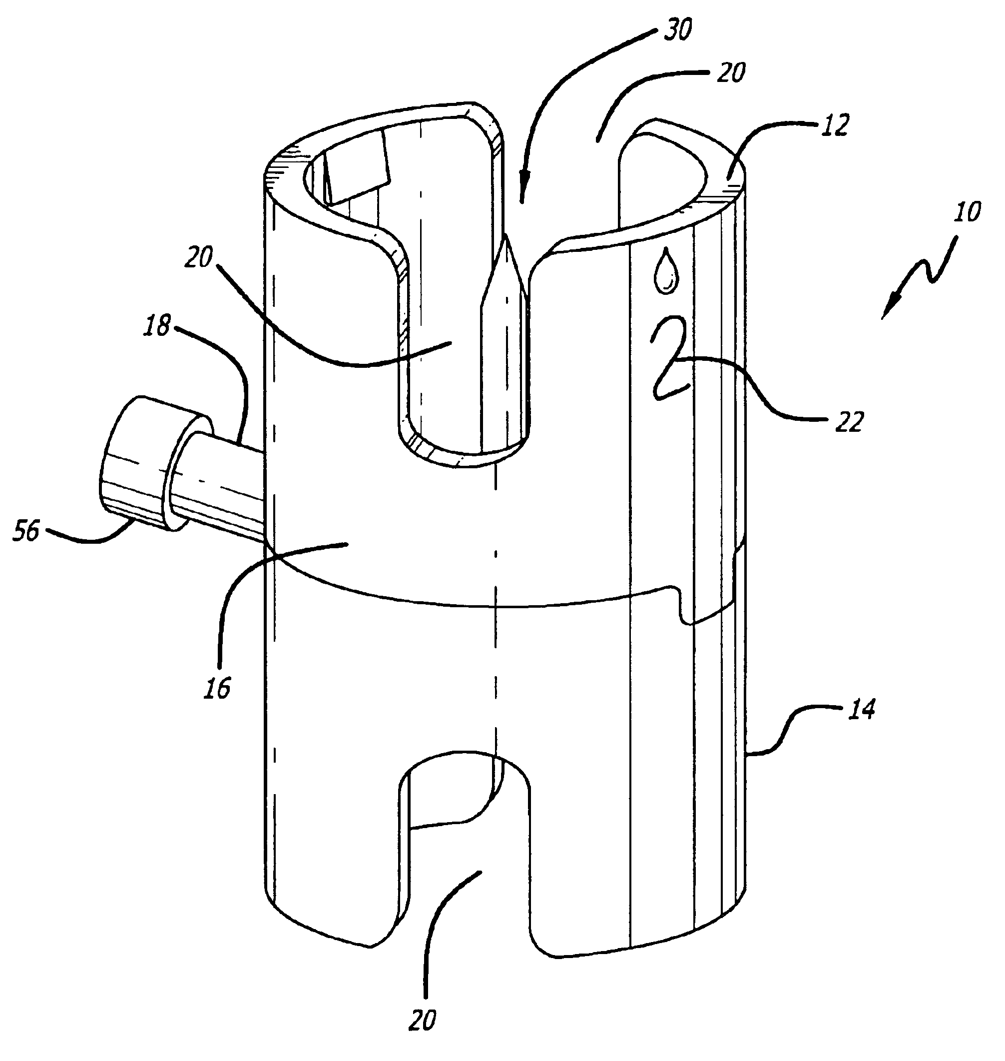
[0022]The reconstitution device disclosed herein is used to facilitate the transfer of components between separate component containers. More particularly, the reconstitution device permits the user to create a pressure differential between a first component container and a second component container thereby permitting the efficient transfer of materials between the component containers. In one embodiment, the reconstitution device enables the operator to transfer materials from commercially available component containers with reduced turbulence and increased user safety while greatly reducing the likelihood...


PUM

PropertyMeasurementUnit
Timeaaaaaaaaaa

Abstract

A reconstitution device is disclosed and includes a first container receiver having a first component cannula disposed therein, the first component cannula having a withdrawal port and a first transfer port formed thereon, a second container receiver having a second component cannula disposed thereon, the second component cannula having a vent port and a second transfer port formed thereon, a device body coupling the first container receiver to the second container receiver and having a transfer lumen formed therein, the transfer lumen in fluid communication with the first and second transfer ports, a selectively sealing interface secured to the device body and in fluid communication with the withdrawal port, and a venting member in communication with the vent port through a vent lumen.

Description

BACKGROUND OF THE INVENTION[0001]Many drugs administered to patients comprise a compound of medicament components mixed shortly before use. Oftentimes it is necessary to store these substances in separate containers until use. Reconstitution of the compound may require the mixing of a liquid-phase component and a solid-phase component, or the mixing of two liquid-phase components. Commonly, the solid-phase component is in powder form to permit stable storing of a component. The containers used to store these components may be constructed of glass, plastic, or other suitable material.[0002]One way currently used to reconstitute materials requires a first component to be injected with a syringe into a container containing a second component. For example, a syringe having a needle attached thereto is inserted through the rubber membrane top of a container containing a first liquid-phase component. Thereafter, the first liquid-phase component is withdrawn into the syringe barrel. The ne...

Claims


Application Information

Patent Timeline
IPC IPC(8): A61J1/00A61J1/20
CPCA61J1/2089A61J2001/2013A61J2001/2055A61J2001/2058A61J2001/2075A61J2001/2082A61J1/201A61J1/2013A61J1/2055A61J1/2058A61J1/2075A61J1/2082Y10T137/8122Y10T137/8342Y10T137/8622
Inventor NEWBROUGH, JERRY W.SLEPICKA, JAMES S.BILSTAD, ARNOLD C.DEFOGGI, JOHN MARKBOSCHELLI, MARIANNE M.JANDRISITS, ALICE M.WU, BIHONG
Owner TAKEDA PHARMA CO LTD
Why Eureka
Try Eureka