Stabilizer bar having variable torsional stiffness

a stabilizer bar and variable torsional technology, applied in the direction of shock absorbers, torsion springs, transportation and packaging, etc., can solve the problems of reducing the ride, affecting the stability of the suspension bar, and being more uncomfortable than it could otherwise, and requiring high stiffness

Active Publication Date: 2005-09-27
THE TIMKEN CO
View PDF19 Cites 38 Cited by
  • Summary
  • Abstract
  • Description
  • Claims
  • Application Information

AI Technical Summary

Problems solved by technology

While a stabilizer bar will improve the control and orientation of a vehicle when the vehicle negotiates a turn, particularly at high speeds on paved surfaces, it detracts from the ride when the vehicle travels along straight road surfaces.
Moreover, it makes travel at low speeds, either straight or through turns, more uncomfortable than it could otherwise be.
These conditions require high stiffness.

Method used


Image

  • Stabilizer bar having variable torsional stiffness
  • Stabilizer bar having variable torsional stiffness
  • Stabilizer bar having variable torsional stiffness

Examples


Embodiment Construction

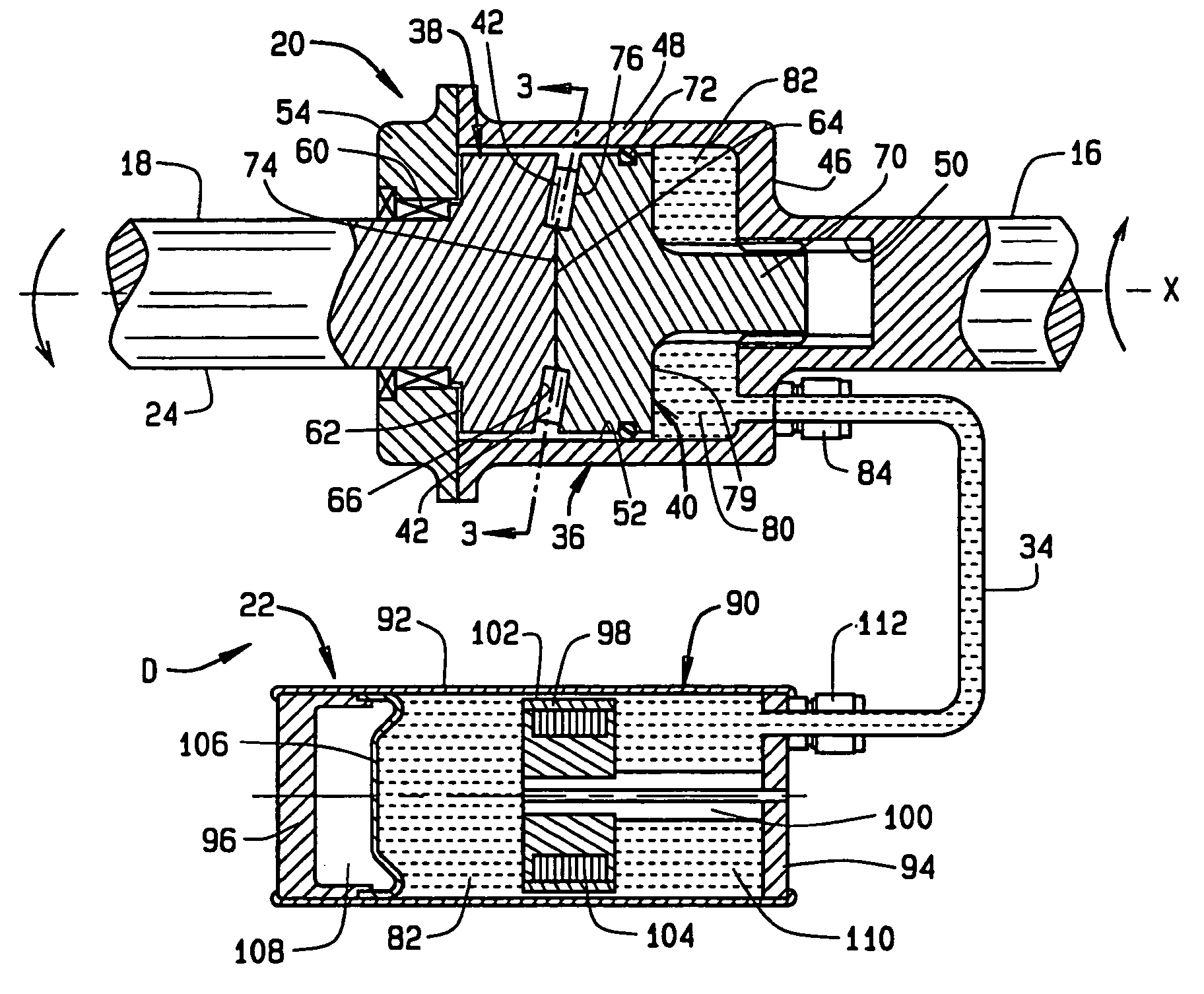
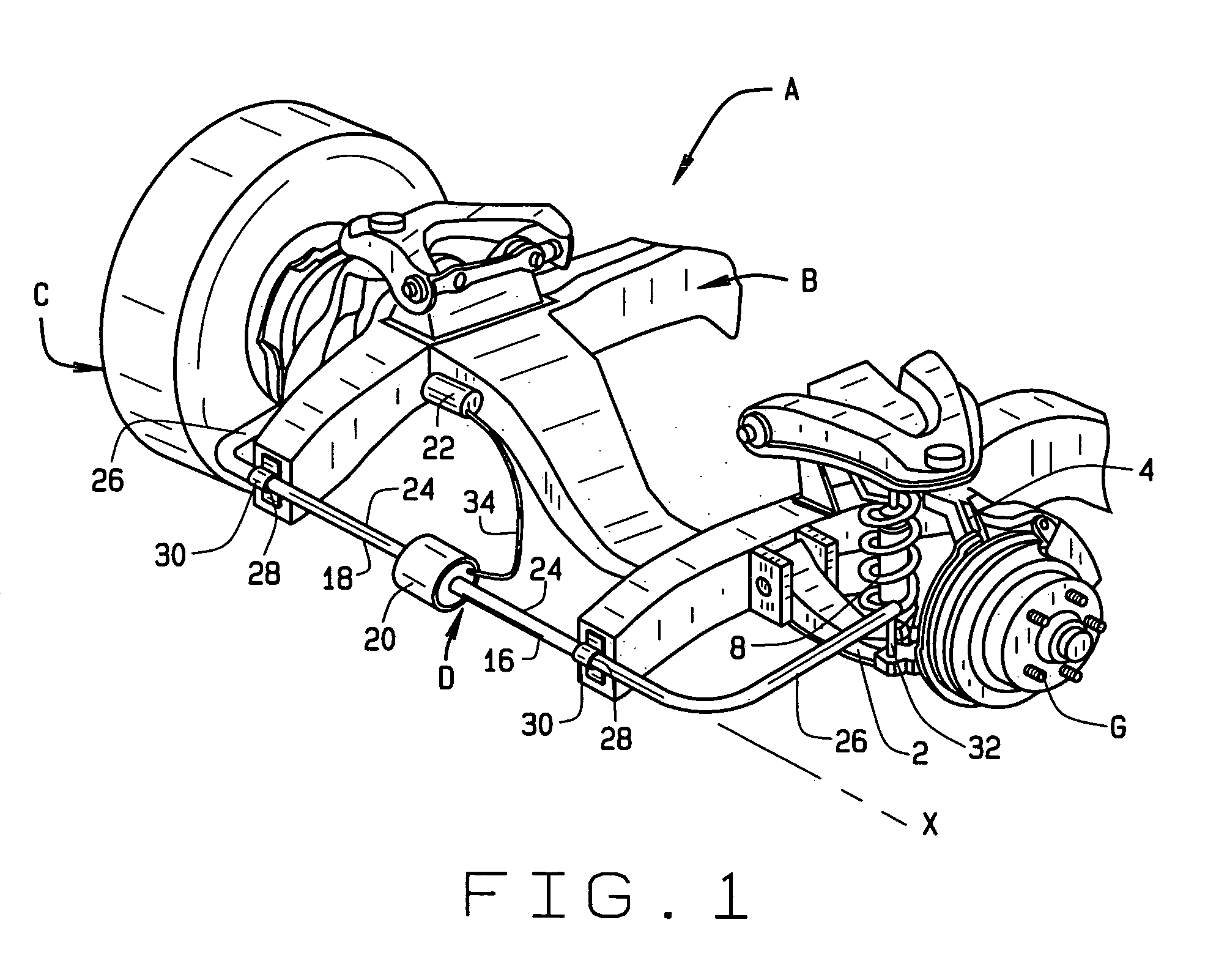
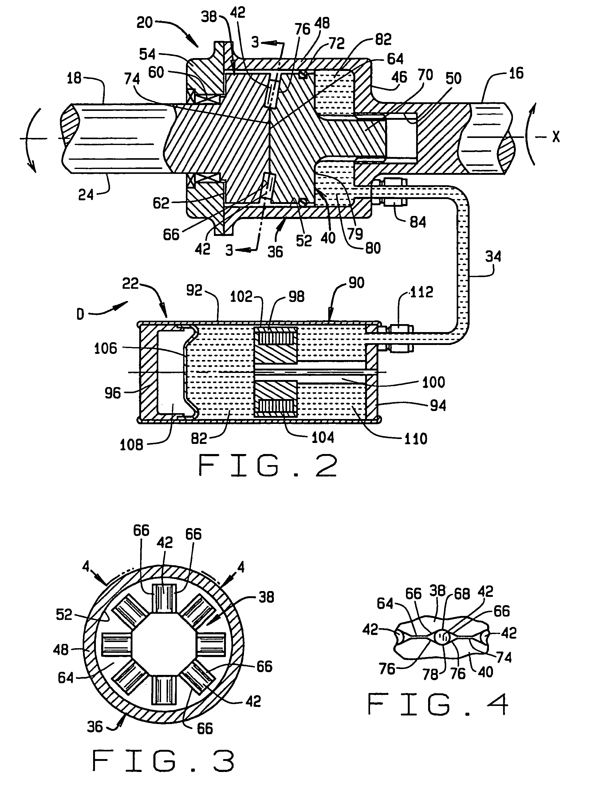
[0011]Referring now to the drawings, an automotive vehicle has a suspension system A (FIG. 1) that is attached to a rigid structural component B, such as a frame or a unified body, of the vehicle. The suspension system A couples left and right road wheels C to the structural component B such that the road wheels C can displace vertically with respect to the structural component B. The suspension system A includes a stabilizer bar D which is attached to both sides of the structural component B and, in effect connects the left and right wheels C. The arrangement is such that when the body of the vehicle rolls—and with it the structural member B—the stabilizer bar D, being extended between the two wheels C, resists the tendency to roll, assuming of course, that it possesses a good measure of torsional stiffness. But when one of the wheels C is displaced vertically, the bar D may transmit a force to the opposite wheel C and that force will urge the opposite wheel C in the same direction...


PUM


Abstract

A stabilizer bar (D) for controlling the roll of an automotive vehicle has left and right sections (16, 18) joined together at a coupling (20) including a housing (36) on one of the sections and on a rotor (38) on the other section, with the rotor being in the housing. The coupling also includes a piston (40) which displaces axially in the housing in response to relative rotation between the sections, and this varies the volume in a housing cavity (80) behind it. That cavity is connected to a valve (22) having a restrictor (98) that carries an electrical coil (104). Both the valve and housing cavity contain a rheological fluid (82). The cease with which the piston displaces in the housing controls the stiffness of bar, and that depends on the viscosity of the fluid in the valve. The magnetic field produced by the coil controls the viscosity of the fluid.

Description

CROSS REFERENCE TO RELATED APPLICATIONS[0001]Not applicable.STATEMENT REGARDING FEDERALLY SPONSORED RESEARCH OR DEVELOPMENT[0002]Not Applicable.BACKGROUND OF THE INVENTION[0003]This invention relates to suspension systems for automotive vehicles and more particularly to a stabilizer bar for a suspension system.[0004]The typical passenger automobile has independently suspended front wheels, as do similar vehicles, such as sports utility vehicles, vans, and light trucks. In order to prevent excessive body roll in such vehicles when they negotiate turns, particularly at higher speeds, the vehicles are equipped with stabilizer bars that connect the sides of their front suspensions. Each side on such a vehicle includes at least one control arm and a steering knuckle to which a wheel end is attached, with one of the front wheels being mounted on the wheel end. The stabilizer bar constitutes nothing more than a torsion bar that extends transversely across the front of the vehicle where it ...

Claims


Application Information

Patent Timeline
Patent Type & Authority Patents(United States)
IPC IPC(8): B60G17/015B60G17/016B60G21/00B60G21/055F16F9/53
CPCB60G21/0556F16F2224/045
Inventor GRADU, MIRCEA
Owner THE TIMKEN CO
Why Eureka
Try Eureka