Matrix connector

a technology of matrix connector and matrix connector, which is applied in the direction of coupling device connection, coupling contact member, coupling device details, etc., can solve the problems of low mechanical strength of the surface the difficulty of connecting an integrated circuit with metal terminals to a circuit board by smt or dip, and the difficulty of using solder balls to substitute metal terminals to test the integration circuit after packaging. , to achieve the effect of preventing deformation of the solder ball

Inactive Publication Date: 2005-09-27
SPEED TECH
View PDF4 Cites 15 Cited by
  • Summary
  • Abstract
  • Description
  • Claims
  • Application Information

AI Technical Summary

Benefits of technology

[0012]The present invention has been accomplished under the circumstances in view. It is the main object of the present invention to provide a matrix connector, which can be used for IC test as well as used as a LGA (Land Grid Array) connector. It is another object of the present invention to provide a matrix connector, which produces low contact stress between the terminal sets and the IC or circuit board during test, preventing deformation of solder balls of the IC. It is another object of the present invention to provide a matrix connector, which prevents an error of contact upon connection of the terminal sets to an IC or printed circuit board having an uneven surface.

Problems solved by technology

Due to high terminal density, it is difficult to connect an integrated circuit with metal terminals to a circuit board by SMT or DIP in mass production.
However, the use of solder balls to substitute for metal terminals complicates test of integrated circuits after packaging.
Because the surface of a solder ball has low mechanical strength and is soft, the terminals of a connector clamp on the solder balls of an integrated circuit may deform the solder balls or force the solder balls away from the integrated circuit.
However, this design is not reliable because the terminal design may cause a shot circuit easily.

Method used


Image

  • Matrix connector
  • Matrix connector
  • Matrix connector

Examples


first embodiment

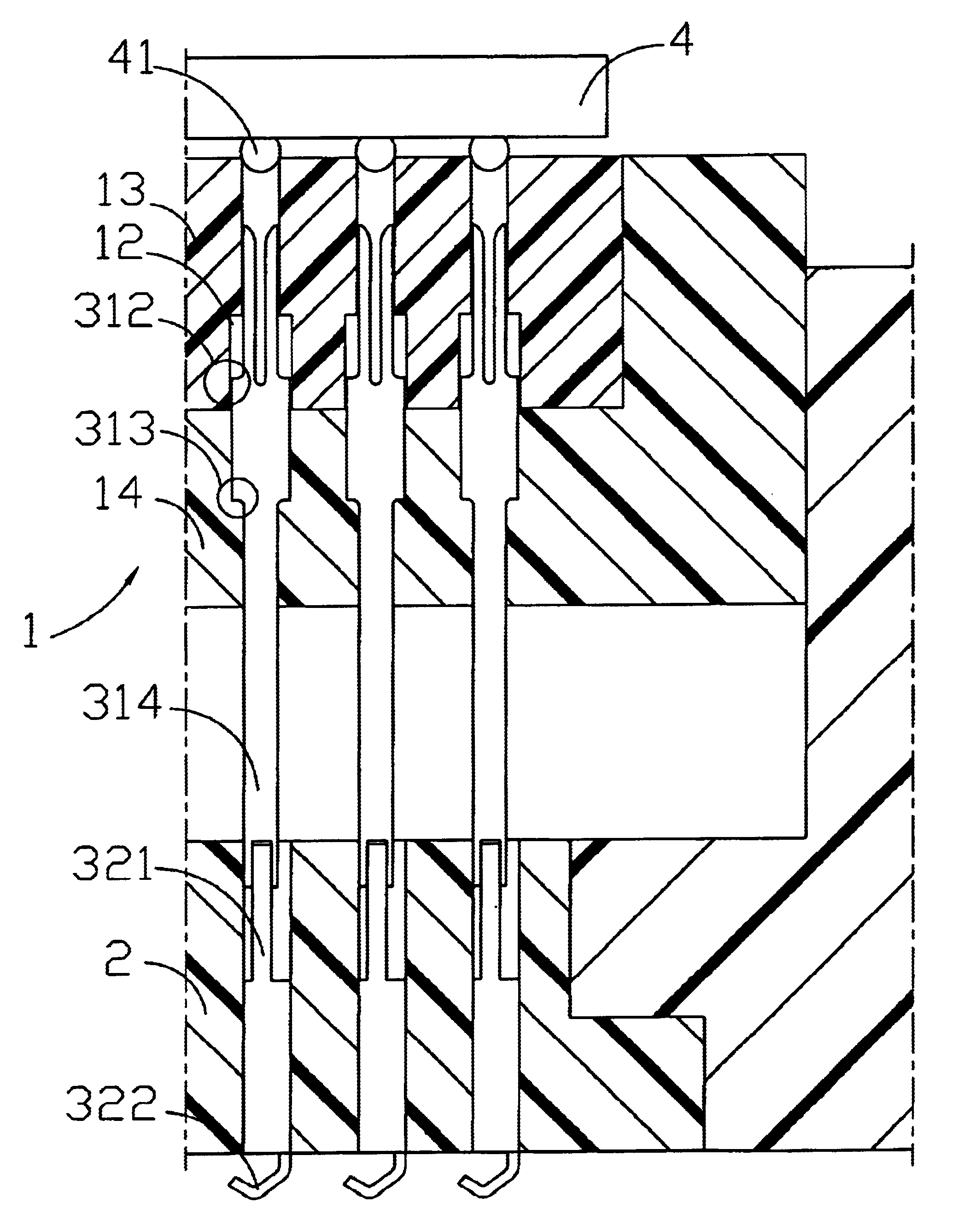
[0028]Referring to FIGS. 1˜3, a matrix connector in accordance with the present invention is shown comprised of a first electrically insulative housing 1, a second electrically insulative housing 2, and a plurality of terminal sets 3.

[0029]The first electrically insulative housing 1 defines therein a plurality of terminal slots 11. The second electrically insulative housing 2 defines therein a plurality of terminal slots 21 corresponding to the terminal slots 11 of the first electrically insulative housing 1.

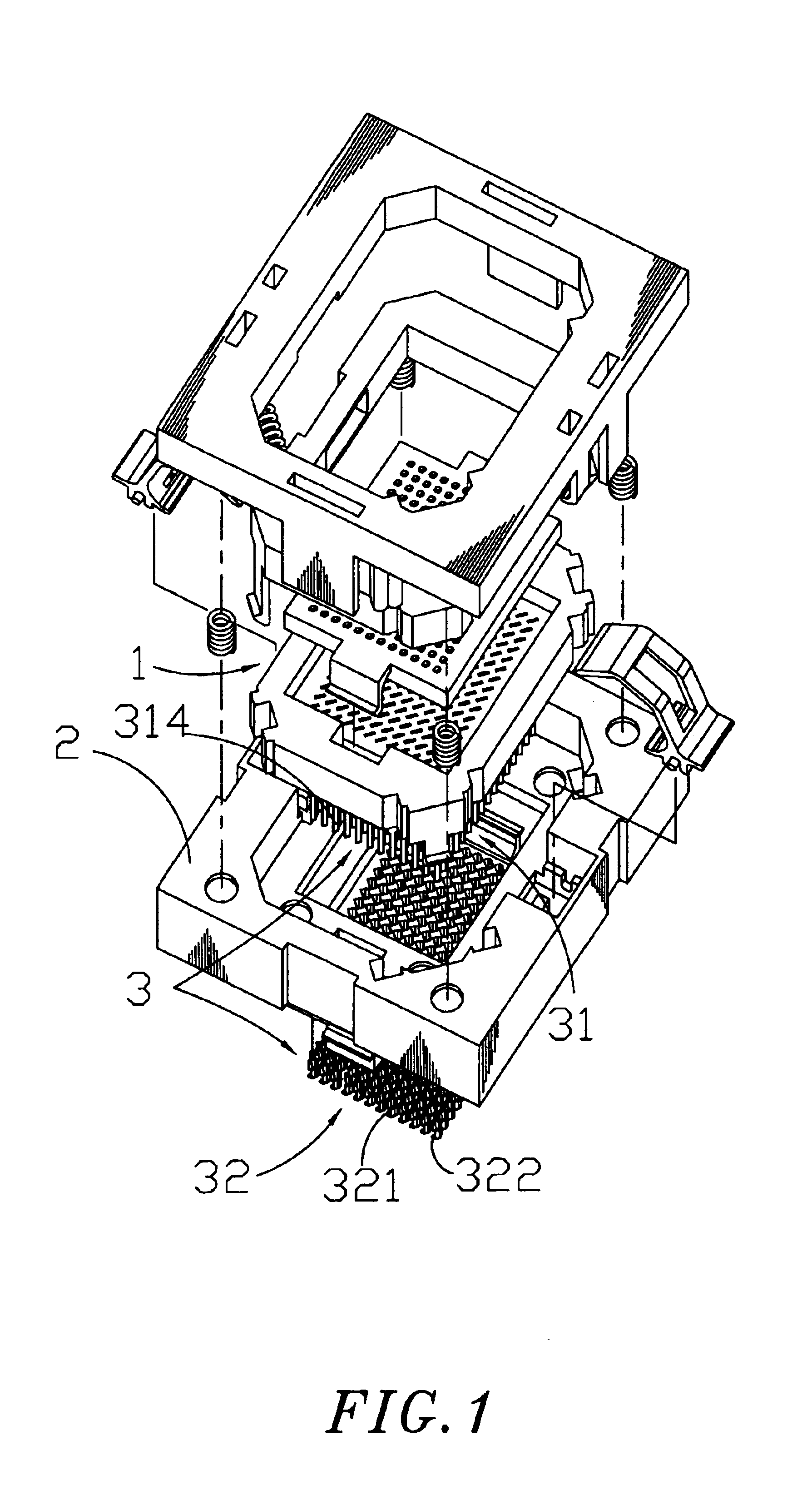
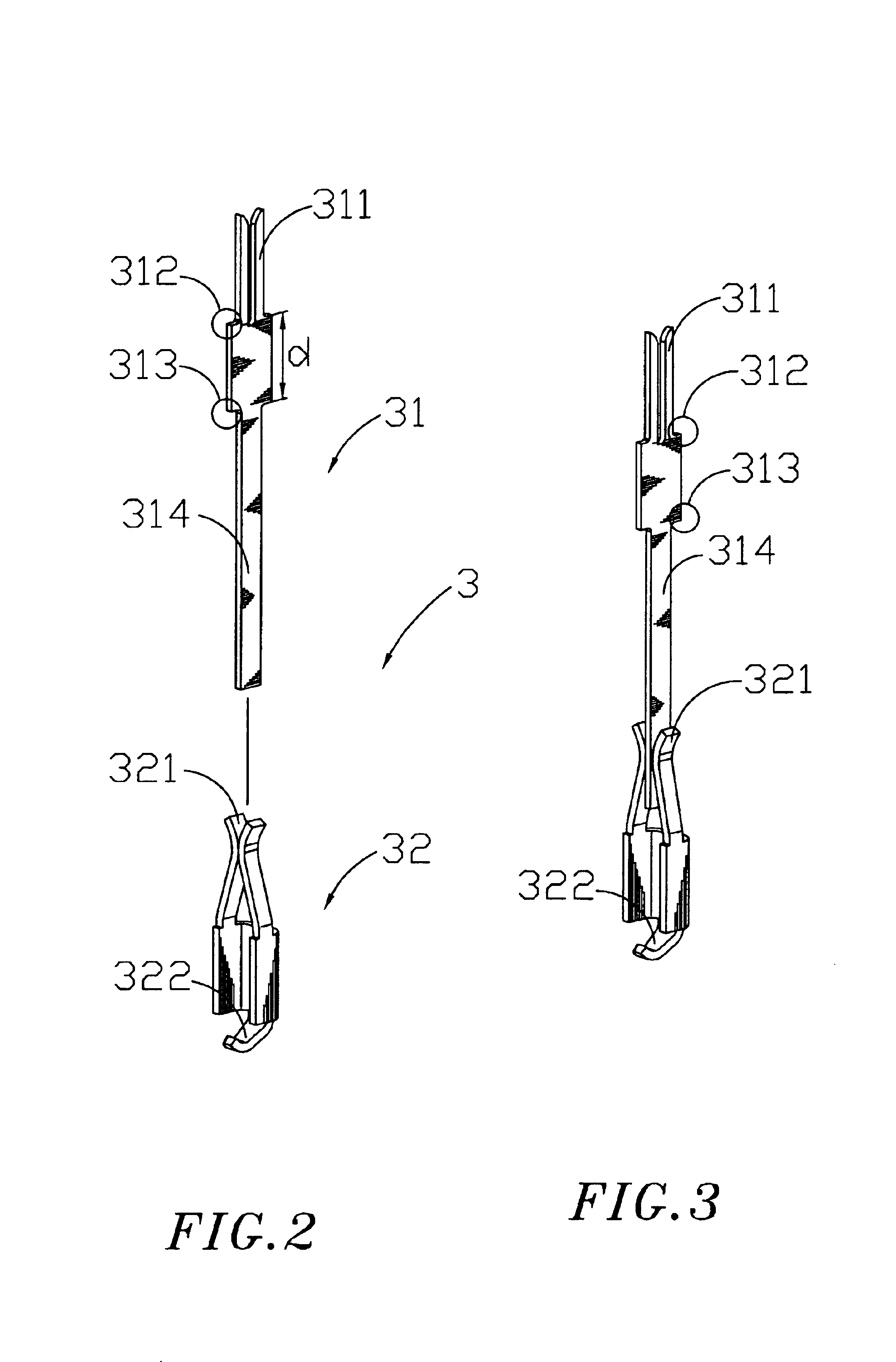
[0030]The terminal sets 3 each comprise a movable terminal 31 and a terminal holder 32. The movable terminal 31 is suspended in one terminal slot 11 of the first electrically insulative housing 1, having an axially forwardly extended front contact portion 311, which is extended to the top end of the corresponding terminal slot 11 and electrically connectable to one solder ball 41 of an IC 4 above the first electrically insulative housing 1. The terminal holder 32 is mounted in t...

second embodiment

[0035]FIGS. 7 and 8 show an alternate form of the terminal set 3. According to this alternate form (i.e., the present invention), the terminal holder 32 comprises two front clamping arms 321 defined therebetween a longitudinally forwardly extended guiding crevice 323 adapted to accommodate the endpiece 314 of the movable terminal 31 and to guide movement of the movable terminal 31 relative to the terminal holder 32. The shortest width of the guiding crevice 323 between the clamping arms 321 is slightly smaller than the thickness of the endpiece 314 of the movable terminal 31, ensuring positively electrical contact between the endpiece 314 of the movable terminal 31 and the clamping arms 321 of the terminal holder 32.

third embodiment

[0036]FIGS. 9 and 10 show another alternate form of the terminal set 3. According to this embodiment (i.e., the present invention), the rear extension portion 322 of the terminal holder 32 extends directly downwards for insertion through the circuit board 5, i.e., the terminal holder 32 forms a DIP terminal convenient for fixation to the circuit board 5.


PUM


Abstract

A matrix connector includes a first electrically insulative housing and a second electrically insulative housing arranged in a stack with the respective terminal slots respectively aligned, and terminals sets each formed of a movable terminal axially slidably mounted in the terminal slots of the first electrically insulative housing and a terminal holder mounted in the terminal slots of the second electrically insulative housing and clamped on the respective movable terminal for enabling the respective movable terminal to be moved axially relative to the respective terminal holder when maintained in contact with the respective terminal holder.

Description

BACKGROUND OF THE INVENTION[0001]1. Field of the Invention[0002]The present invention relates to a matrix connector adapted for testing integrated circuits or circuit boards having high terminal density and more particularly, to such a matrix connector, which produces low contact stress, prevents deformation of solder balls, and allows a big tolerance of flatness of contact surface.[0003]2. Description of the Related Art[0004]The terminals of conventional integrated circuits are commonly made of metal. Therefore, the terminals of conventional integrated circuits have good mechanical strength, and test connectors can be electrically connected to the terminals of integrated circuits by clamping. An integrated circuit having metal terminals can be electrically connected to the internal circuit of an electronic device by SMT or DIP.[0005]In recent years, conventional integrated circuits are made having a high terminal density. Due to high terminal density, it is difficult to connect an ...

Claims


Application Information

Patent Timeline
Patent Type & Authority Patents(United States)
IPC IPC(8): H01R13/115H01R13/24H01R13/22H01R13/11
CPCH01R13/112H01R13/2421H01R2201/20
Inventor CHEN, LI-SENHSU, CHIEN-YULIAO, YEN-JANG
Owner SPEED TECH
Why Eureka
Try Eureka