Guide wire steering handle

a technology of steering handle and guide wire, which is applied in the field of guide wire steering devices, can solve the problems of coatings becoming more slippery, difficult and time-consuming to insert and manipulate guidewires, and difficult to ensure the safety of the coating

Inactive Publication Date: 2005-09-27
GRIFFIS JACK +1
View PDF18 Cites 121 Cited by
  • Summary
  • Abstract
  • Description
  • Claims
  • Application Information

AI Technical Summary

Benefits of technology

[0017]It is still a further object of the present invention to provide a guidewire steering device wherein the first end of the first gripping surface is coupled to the first end of the second gripping surface permitting controlled movement of the first and second gripping surfaces toward each so as to selectively grip a guidewire positioned therebetween.

Problems solved by technology

Insertion and manipulation of guidewires is often difficult and time consuming.
Handling of guidewires is further complicated by the fact that conventional guidewires are generally provided with protective coatings that prevent blood from clotting on the guidewire, improve biocompatibility and enhance the guidewires maneuverability through the vascular system.
However, such coatings often become more slippery when wetted, particularly with blood.
With this in mind, and in consideration of the size and material characteristics of conventional guidewires, it is extremely difficult to accurately and precisely handle and manipulate (e.g., pinch and torque) these small diameter guidewires with the fingers.
However, these prior art steering devices are replete with shortcomings which often frustrate physicians and limit procedure success.

Method used


Image

  • Guide wire steering handle
  • Guide wire steering handle
  • Guide wire steering handle

Examples


Embodiment Construction

[0036]The detailed embodiment of the present invention is disclosed herein. It should be understood, however, that the disclosed embodiment is merely exemplary of the invention, which may be embodied in various forms. Therefore, the details disclosed herein are not to be interpreted as limiting, but merely as the basis for the claims and as a basis for teaching one skilled in the art how to make and / or use the invention.

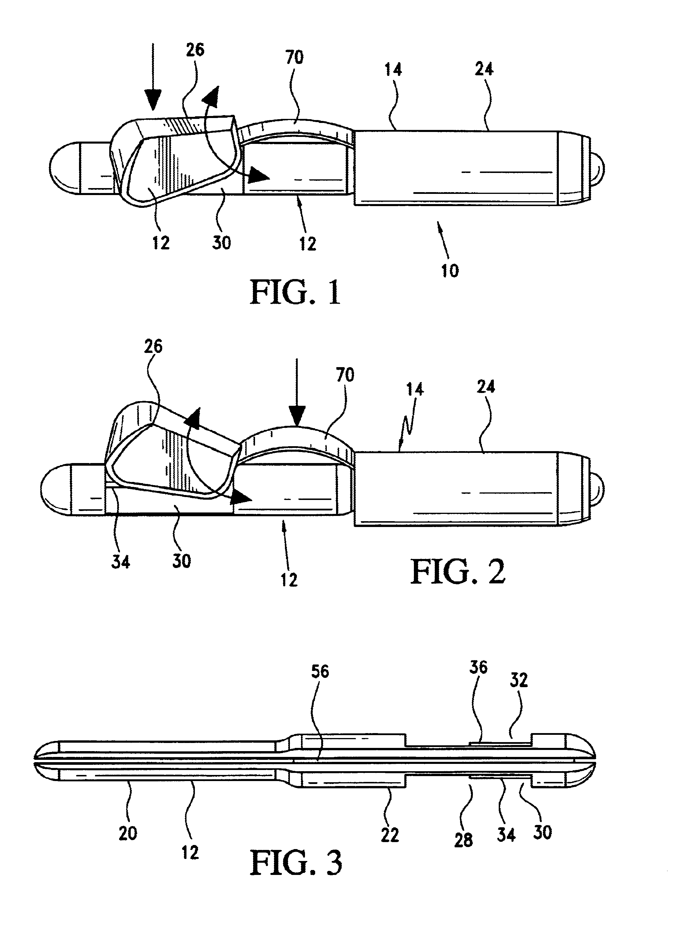
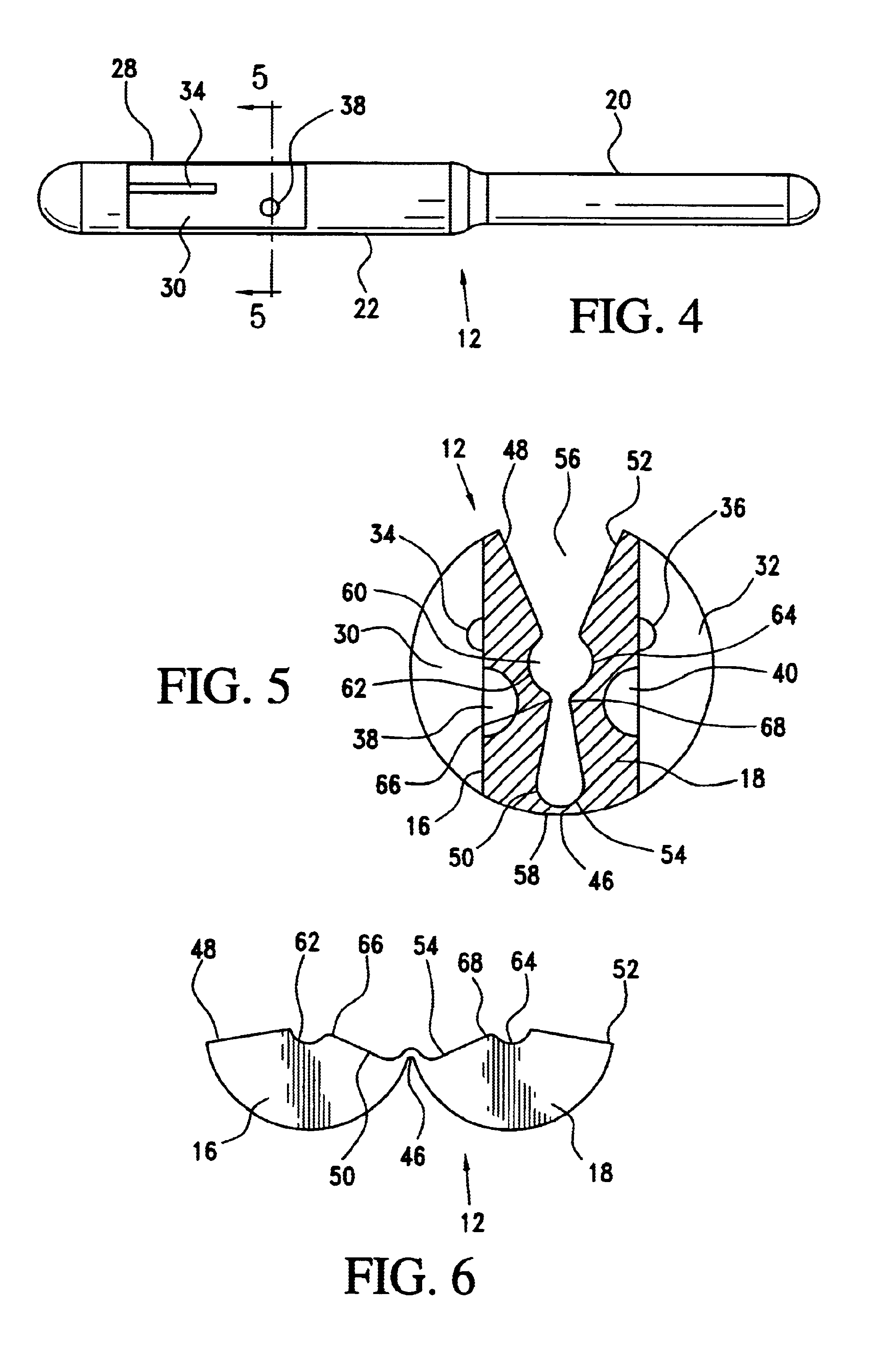
[0037]With reference to FIGS. 1 to 9, a guidewire steering device 10 in accordance with the present invention is disclosed. The guidewire steering device 10 generally includes a gripping member 12 and a compression member 14. In use, the compression member 14 straddles the flexing portion of the gripping member 12 to facilitate one handed loading and maneuvering of the present guidewire steering device 10. That is, the compression member 14 controls movement of the gripping member 12 between a gripping orientation in which first and second gripping surfaces 16, 18 en...


PUM


Abstract

A guidewire steering device includes a gripping member and a compression member. The gripping member includes opposed first and second gripping surfaces positioned for selective engagement of a guidewire positioned therebetween. The first gripping surface includes a first end and a second end and the second gripping surface includes a first end and a second end. The first and second gripping surfaces being oriented to permit selective gripping of a guidewire positioned therebetween. The second end of the first gripping surface and the second end of the second gripping surface are spaced apart in a manner defining a lateral access slot through which a guidewire may be passed for positioning between the first and second gripping surfaces. The compression member is positioned about the gripping member for controlling movement of the first and second gripping surfaces between a gripping orientation in which the first and second gripping surfaces engage a guidewire positioned therebetween and a sliding orientation in which the first and second gripping surfaces are sufficiently spaced to permit free movement of a guidewire therebetween. The compression member includes first and second outwardly extending arms which respectively wrap about an exterior surface of the gripping member adjacent the first and second gripping surfaces to force the first and second gripping surfaces toward each other when the compression member is moved toward the gripping member.

Description

BACKGROUND OF THE INVENTION[0001]1. Field of the Invention[0002]The invention relates to guidewire steering devices. More particularly, the invention relates to side loading guidewire steering devices adapted for one-hand manipulation.[0003]2. Description of the Prior Art[0004]Interventional medical procedures involving guidewire introduction, insertion and manipulation are well known. For example, angioplasty generally includes the steps of inserting a guidewire through a vascular access needle into the femoral artery, and manipulating the external proximal end of the guidewire to advance the distal end of the guidewire through the patient's arterial tree to a predetermined vascular destination. A conventional dilatation, or other percutaneous catheter is then easily and rapidly fed over the guidewire directly into the vasculature to perform an appropriate diagnostic or therapeutic procedure. Similar guidewire applications are utilized in the introduction, removal and / or exchange o...

Claims


Application Information

Patent Timeline
Patent Type & Authority Patents(United States)
IPC IPC(8): A61F11/00A61M25/01A61M25/09
CPCA61M25/09A61M2025/09116
Inventor GRIFFIS, JACKGIANNESCHI, PAUL
Owner GRIFFIS JACK
Why Eureka
Try Eureka