Parking assist system with image obtaining means and displaying means

Inactive Publication Date: 2005-09-27
AISIN SEIKI KK
View PDF12 Cites 158 Cited by
  • Summary
  • Abstract
  • Description
  • Claims
  • Application Information

AI Technical Summary

Problems solved by technology

However, according to the parking assist system, the vehicle sometimes can not be parked at the intende

Method used


Image

  • Parking assist system with image obtaining means and displaying means
  • Parking assist system with image obtaining means and displaying means
  • Parking assist system with image obtaining means and displaying means

Examples


Embodiment Construction

[0021]An embodiment of the present invention will be described hereinbelow in detail with reference to the accompanying drawings.

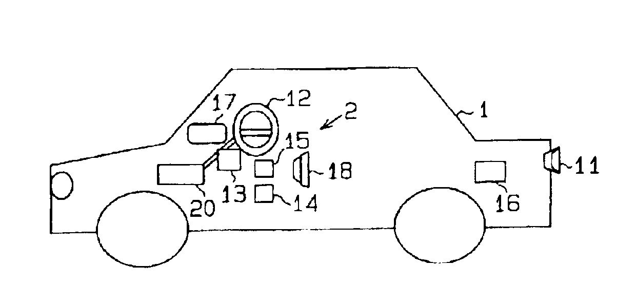
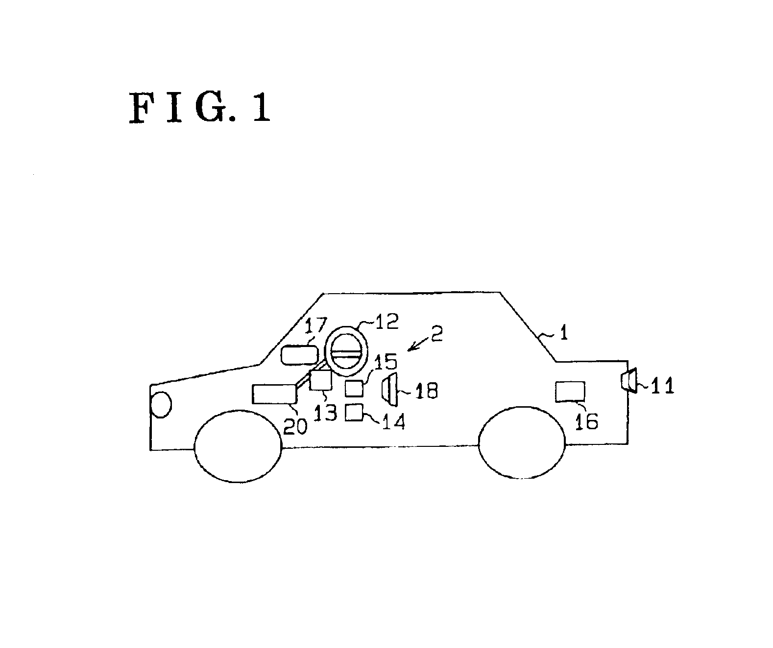
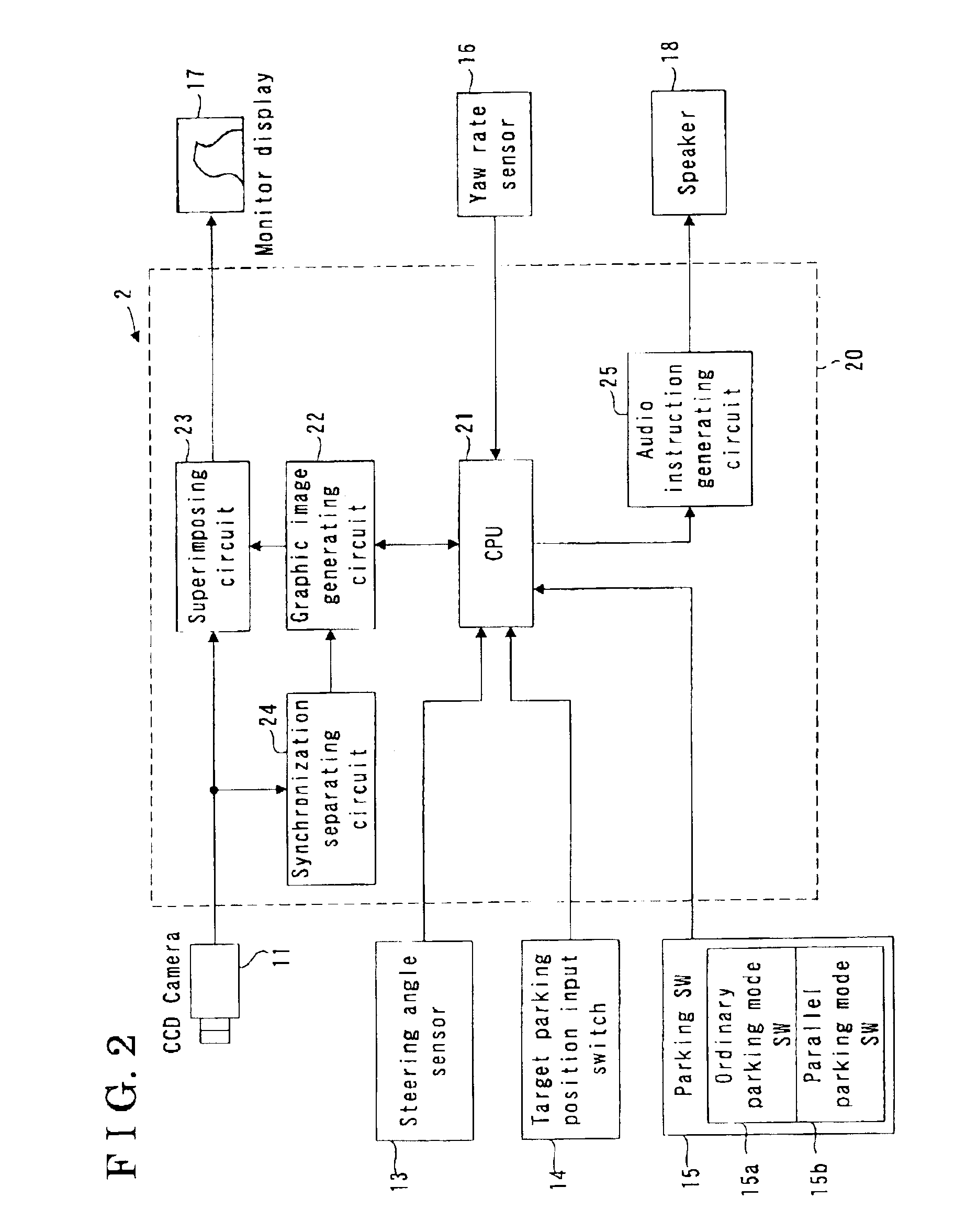
[0022]As seen in FIG. 1, a parking assist system 2 is installed on a vehicle 1. The parking assist system 2 is provided with a camera (a charge-coupled device camera, i.e. a CCD camera) 1, a steering wheel 12, a steering angle sensor 13, a target parking position input switch 14 (i.e. a target parking position inputting means), a parking switch 15, a yaw rate sensor 16, a back-view monitor display 17, a speaker 18, and a controller 20. The camera 11 functions as an image obtaining means and obtains a vehicle rear view when the vehicle 1 is moving in a rearward direction. The camera 11 outputs an image data in response to the obtained vehicle rear view to the controller 20. The camera 11 is provided at an approximately center of a rear portion of the vehicle 1 with an optic axis directed in a vertically downward direction. More particularly, as illustrated ...


PUM


Abstract

A parking assist system includes an image obtaining means for obtaining an image of a view from a vehicle, a displaying means for displaying the image obtained by the image obtaining means in a monitor display provided in the vehicle, an inputting means for inputting a target parking position, at which the vehicle is parked, on the monitor display, a detecting means for detecting a relative relationship between the vehicle and the target parking position, and a judging means for judging whether or not the vehicle can be parked at the target parking position based upon the relative relationship detected by the detecting means.

Description

CROSS REFERENCE TO RELATED APPLICATIONS[0001]This application is based on and claims priority under 35 U.S.C. §119 with respect to a Japanese Patent Application 2002-105769, filed on Apr. 8, 2002, the entire content of which is incorporated herein by reference.FIELD OF THE INVENTION[0002]This invention generally relates to a parking assist system.BACKGROUND OF THE INVENTION[0003]A conventional parking assist system for assisting a driver's parking operation has been disclosed in a Japanese Patent Laid-open published as No. 1999-334470, in which an image of a view in a vehicle moving direction captured by a camera is shown on a monitor display installed in a vehicle. More particularly, the disclosed parking assist system assists the driver's parking operation by superposing an expected vehicle moving path in response to a steering angle of a steering handle on the back view captured by the camera. Therefore, the driver turns the steering handle so as to park the vehicle at a predeter...

Claims


Application Information

Patent Timeline
IPC IPC(8): B62D15/02B62D15/00B60Q1/48B60R1/00B60Q1/26G01S5/16G01S5/00G03B15/00B60R21/00
CPCB60Q9/004B60R1/00B62D15/027B60R2300/305B60R2300/806B60T2201/10G01S5/16
Inventor TANAKA, YUUIWATA, YOSHIFUMISATONAKA, HISASHIENDO, TOMOHIKOMORITA, MITSUHIKOIWAZAKI, KATSUHIKOKAWAKAMI, SEIJIKATAOKA, HIROAKI
Owner AISIN SEIKI KK
Why Eureka
Try Eureka