Battery life indication

Inactive Publication Date: 2005-09-27
NOKIA TECHNOLOGLES OY
View PDF11 Cites 16 Cited by
  • Summary
  • Abstract
  • Description
  • Claims
  • Application Information

AI Technical Summary

Benefits of technology

[0007]It is an object of the present invention to solve or at least ameliorate the aforementioned problems. It will be appreciated that the pre

Problems solved by technology

This has the advantage of being relatively simple to implement but suffers from a lack of accuracy.
A problem therefore arises with the approach to extant battery life determination described in GB-A-2312517 in that the result is not available for several minutes after the first voltage readi

Method used


Image

  • Battery life indication
  • Battery life indication
  • Battery life indication

Examples


Embodiment Construction

[0045]Embodiments of the present invention will now be described, by way of example, with reference to the accompanying drawings.

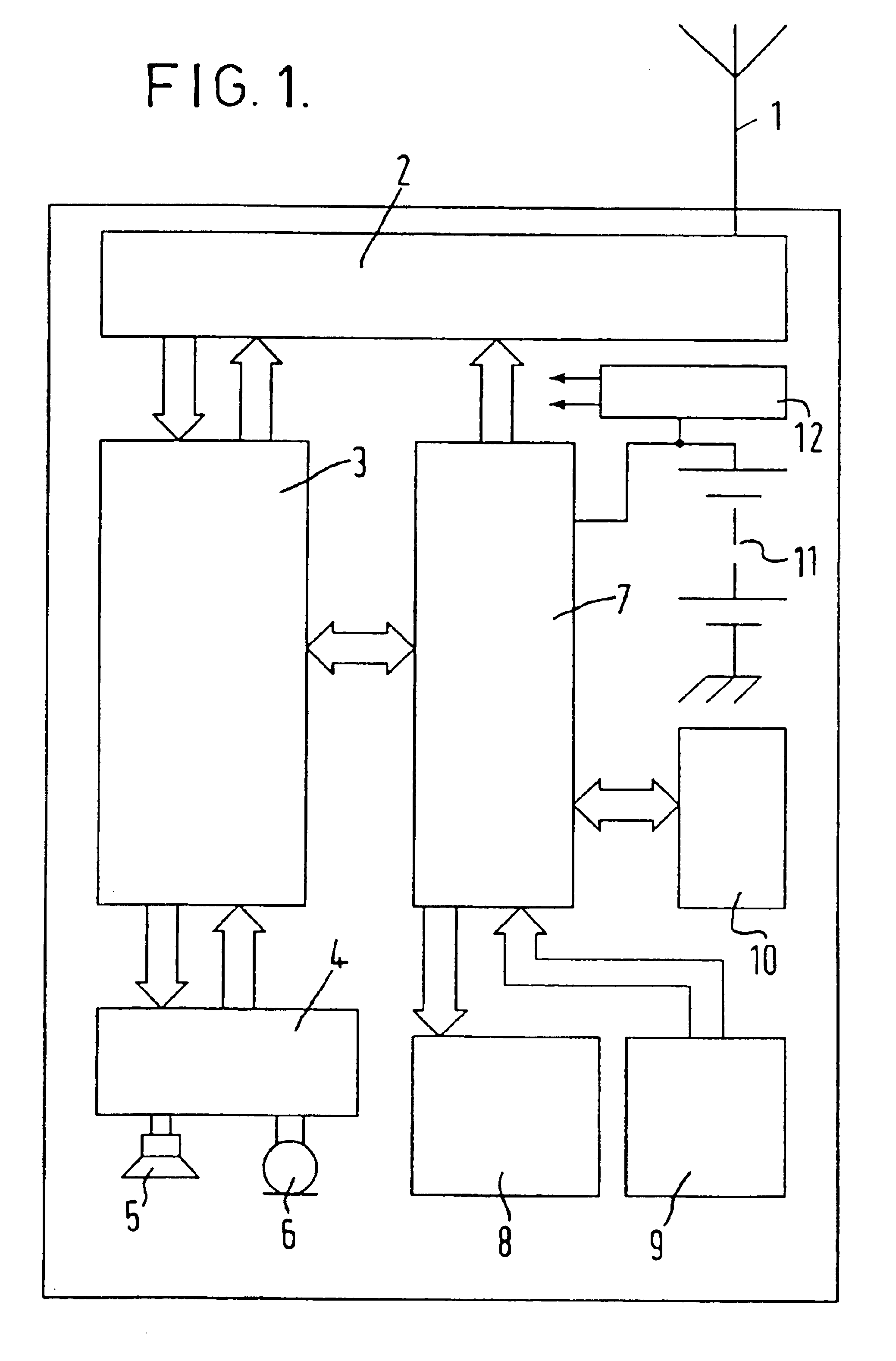
[0046]Referring to FIG. 1, a mobile telephone comprises an antenna 1, an rf subsystem 2, a baseband DSP (digital signal processing subsystem 3, an analogue audio subsystem 4, a loudspeaker 5, a microphone 6, a controller 7, a liquid crystal display 8, a keypad 9, memory 10, a battery 11 and a power supply circuit 12.

[0047]The rf subsystem 2 contains if and rf circuits of the mobile telephone's transmitter and receiver and a frequency synthesiser for tuning the mobile telephone's transmitter and receiver. The antenna 1 is coupled to the rf subsystem 2 for the reception and transmission of radio waves.

[0048]The baseband DSP subsystem 3 is coupled to the rf subsystem 2 to receive baseband signals therefrom and for sending baseband modulation signals thereto. The baseband DSP subsystems 3 includes codec functions which are well-known in the art.

[0049]The analo...


PUM


Abstract

A method of indicating extant battery life has the steps of initially determining a first extant battery life value having a first confidence level and generating a perceivable indication of the first battery life value. The method also has the step of determining a second extant battery life value having a second confidence level and generating a perceivable indication of the second battery life value after generating the perceivable indication of the first battery life value. The second confidence level is higher than the first confidence level and the determination of the first extant battery life value is completed before the determination of the second extant battery life value is completed.

Description

FIELD OF THE INVENTION[0001]The present invention relates to the indication of extant battery life.BACKGROUND OF THE INVENTION[0002]Mobile telephones are an example of a battery-powered device familiar to most people. The extant battery life of battery-power devices, including mobile telephones, is of considerable importance to their users. Consequently, the provision of extant battery life indicators on mobile telephones is universal.[0003]One method of determining the extant battery life of an apparatus, such as a mobile telephone, is to measure the battery voltage and then read an extant battery life value from a pre-programmed lookup table. This has the advantage of being relatively simple to implement but suffers from a lack of accuracy.[0004]This problem is addressed in GB-A-2312517 which describes taking three voltage readings, fitting a discharge curve to the readings and then determining the extant battery life from the curve fitted to the readings. This approach is more ac...

Claims


Application Information

Patent Timeline
IPC IPC(8): G01R31/36
CPCG01R31/362G01R31/3651G01R31/3648G01R31/3693G01R31/3647G01R31/367G01R31/3835
Inventor HUNT, ALLAN
Owner NOKIA TECHNOLOGLES OY
Why Eureka
Try Eureka