Method for resistivity anisotropy determination in near vertical wells

a resistivity anisotropy and well technology, applied in the direction of seismology, waterlogging using reradiation, instruments, etc., can solve the problems of limiting the effectiveness of xiao '619 as a real-time analysis method, limiting the design of lateral logs, and requiring a significant amount of processing time for forward modeling

Inactive Publication Date: 2005-09-27
BAKER HUGHES INC
View PDF20 Cites 24 Cited by
  • Summary
  • Abstract
  • Description
  • Claims
  • Application Information

AI Technical Summary

Problems solved by technology

The method of Xiao '619 requires a significant amount of processing time for forward modeling, data inversion, skin effect corrections, etc.
This limits their effectiveness as a method for real-time analysis.
The lateral log is generally not designed for differentiating horizontal and vertical resistivities in a formation having resistivity anisotropy.
However, since focused galvanic measurements are not very sensitive to changes of the formation resistivity in the vertical direction (Rv)

Method used


Image

  • Method for resistivity anisotropy determination in near vertical wells
  • Method for resistivity anisotropy determination in near vertical wells
  • Method for resistivity anisotropy determination in near vertical wells

Examples


Embodiment Construction

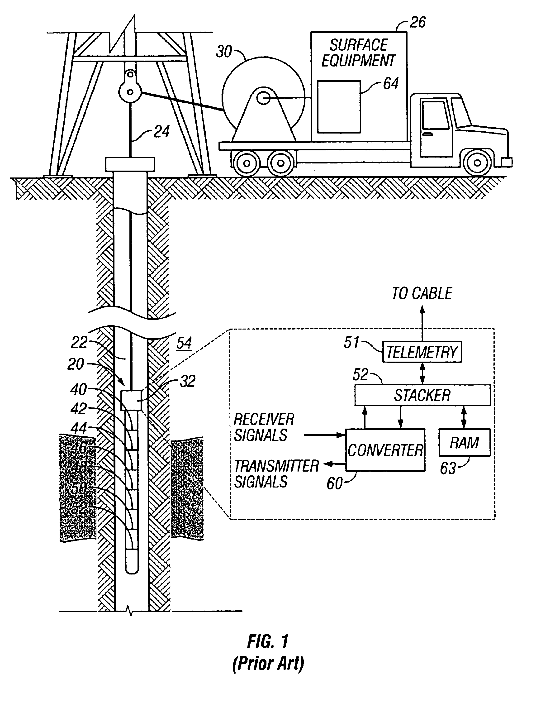
[0029]Referring now to FIG. 1, an induction logging tool 20 suitable for use in the invention described herein is shown positioned in a borehole 22 penetrating earth formations 54. The tool 20, which is suspended in the borehole 22 by means of a wireline cable 24, includes a borehole sonde 34 and an electronic circuitry section 32. The tool 20 is lowered into the borehole 22 by a cable 24, which preferably passes over a sheave 30 located at the surface of the borehole 22. The cable 24 is typically spooled onto a drum (not shown). The cable 24 includes insulated electric conductors for transmitting electrical signals. The electronic circuitry section 32 of the tool 20 receives signals from the sonde section 34 to perform various analog and digital functions, as will be described later.

[0030]The sonde 34 preferably includes a plurality of coils 40-52. Coil 46 is a transmitter coil for transmitting an oscillating signal into the adjacent surrounding geological formation 54. Preferably,...


PUM


Abstract

A method is disclosed for real-time (well-site) resistivity anisotropy determination using array lateral logs or any other unfocused, lateral-type measurements, and array induction logs or any other focused, induction-type measurements. Near-vertical wells with a deviation angle of less than 30 degrees are considered. Since with a lateral log, at each logging depth the injected current has both horizontal and vertical components, the data contains information related to both horizontal (Rh) and vertical (Rv) resistivities. With array induction tool, the induced current in near-vertical wells has only a horizontal component, and the induction data contain information related to Rh only. Having those two data sets acquired in the same well, it is possible to instantly estimate the formation resistivity anisotropy using square of a ratio between borehole and invasion corrected lateral and induction focused logs.

Description

CROSS REFERENCES TO RELATED APPLICATIONS[0001]This applications claims priority from Provisional U.S. Patent Application Ser. No. 60 / 414,174 filed on 27 Sep. 2002.BACKGROUND OF THE INVENTION[0002]1. Field of the Invention[0003]The invention is directed to resistivity anisotropy interpretation systems and methods for well logging application and, in one particular aspect, to a data interpretation system and method that is usable to determine formation parameters and reservoir descriptions in real-time.[0004]2. Description of the Related Art[0005]The production of hydrocarbons from subsurface formations typically commences by forming a borehole through the earth to a subsurface reservoir thought to contain hydrocarbons. From the borehole, various physical, chemical, and mechanical properties are “logged” for the purpose of determining the nature and characteristics, including for example, the porosity, permeability, saturation, and depth of the subsurface formations encountered. One s...

Claims


Application Information

Patent Timeline
IPC IPC(8): G01V3/28G01V3/18G01V3/20
CPCG01V3/20G01V3/28
Inventor FRENKEL, MICHAEL A.GELDMACHER, INGO M.
Owner BAKER HUGHES INC
Why Eureka
Try Eureka