Heat sink assembly incorporating mounting frame

a technology of mounting frame and heat sink, which is applied in the direction of cooling/ventilation/heating modification, semiconductor/solid-state device details, semiconductor devices, etc., can solve the problems of linear clip not being able to firmly retain the heat sink against the cpu, unduly inconvenient, and inability to apply heat grease in advance to the heat sink, etc., to achieve convenient and convenient mounting of the grease cover

Inactive Publication Date: 2005-10-04
HON HAI PRECISION IND CO LTD
View PDF7 Cites 41 Cited by
  • Summary
  • Abstract
  • Description
  • Claims
  • Application Information

AI Technical Summary

Benefits of technology

[0008]Accordingly, an object of the present invention is to provide a heat sink assembly incorporating a mounting frame which can readily and conveniently mount a grease cover to a heat sink.

Problems solved by technology

However, thermal grease cannot be applied to the heat sink in advance since it is not solid at ambient temperature and may contaminate surrounding articles or be contaminated by dust or foreign particles before the heat sink is attached to the CPU.
This is unduly inconvenient.
Another difficulty relating to the attachment of a heat sink to a CPU is as follows.
However, in many modem applications such as when a large heat sink is used, the linear clip cannot firmly retain the heat sink against the CPU.
However, the widened groove takes up space that would otherwise be utilized to provide more fins for the heat sink.
In effect, the plate-type clip reduces a heat dissipating area of the heat sink, and reduces the heat dissipating capability of the heat sink.
However, use of the retention module increases the number of parts of the assembly, and inflates costs.

Method used


Image

  • Heat sink assembly incorporating mounting frame
  • Heat sink assembly incorporating mounting frame
  • Heat sink assembly incorporating mounting frame

Examples


Embodiment Construction

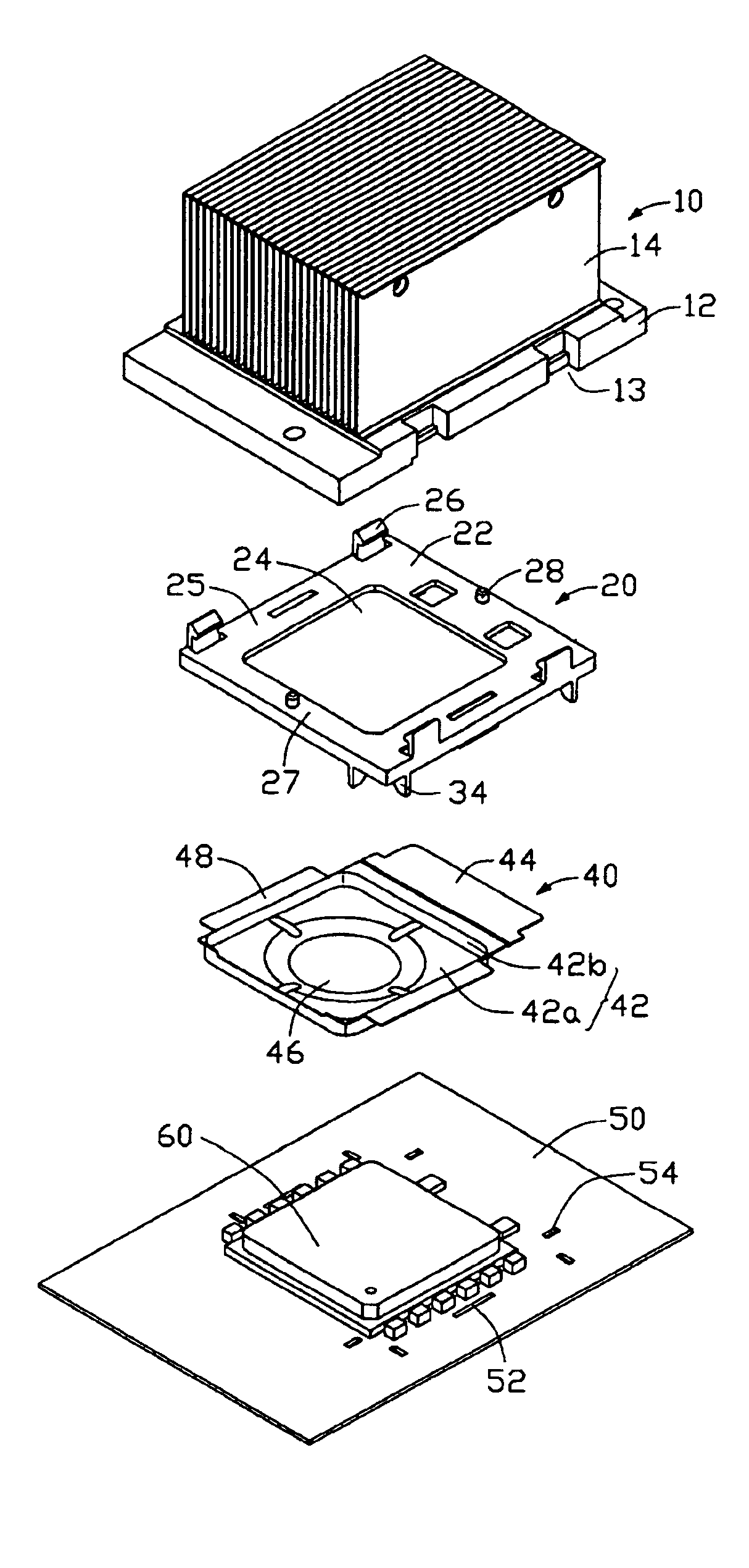
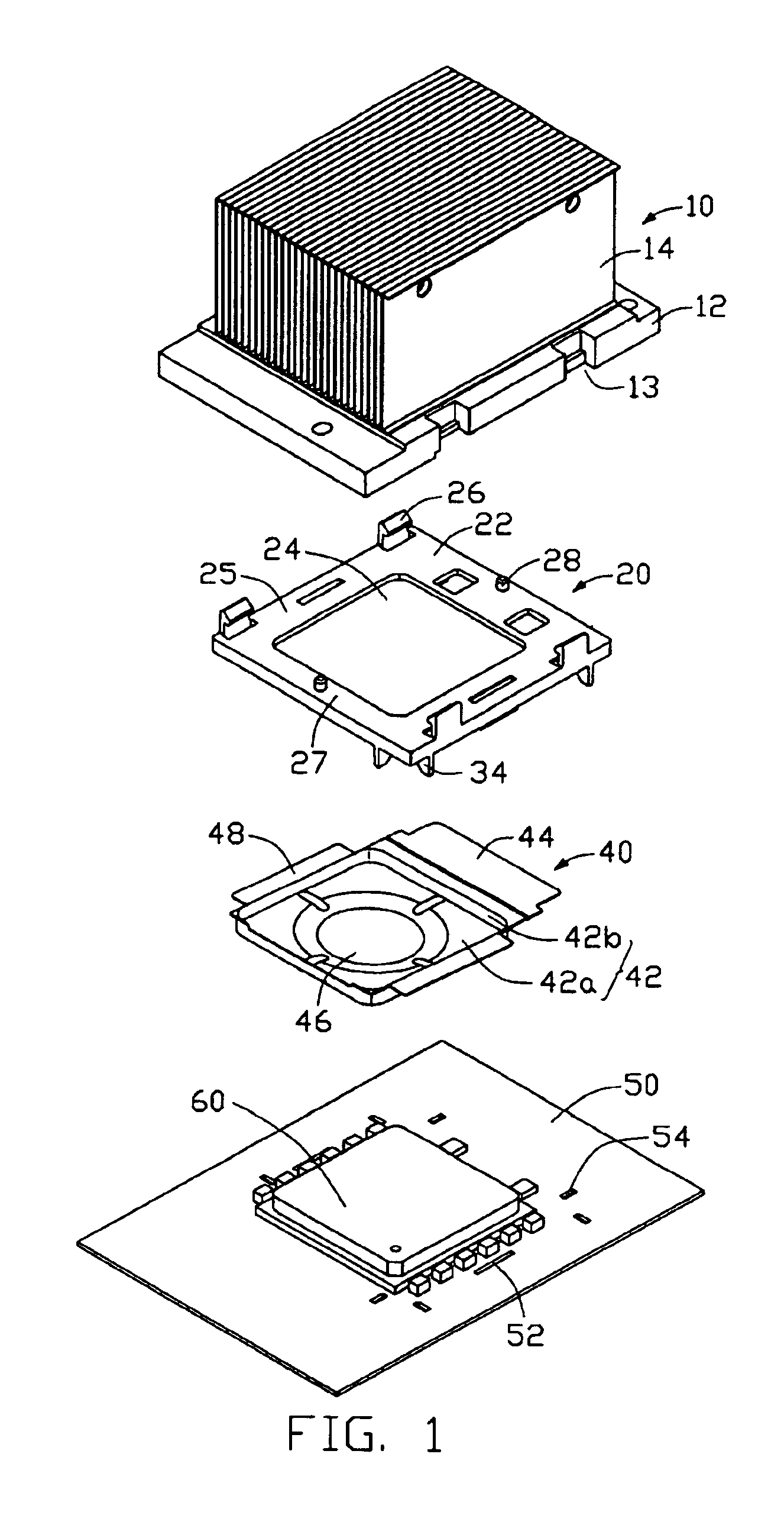
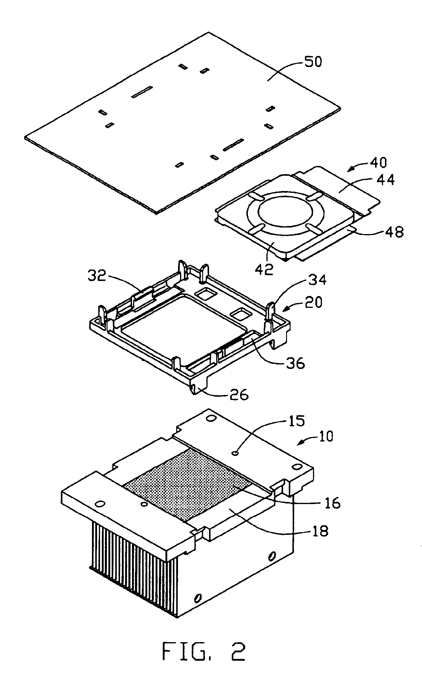
[0016]FIGS. 1-2 show a heat sink assembly in accordance with the preferred embodiment of the present invention, together with an electronic component 60 mounted on a circuit board 50. The electronic component 60 may, for example, be a CPU. A pair of locking slots 52 is defined in the circuit board 50 on opposite longitudinal sides of the electronic component 60 respectively. Four pairs of locating openings 54 are defined in the circuit board 50, adjacent four corners of the electronic component 60 respectively. The locating openings 54 in each pair of locating openings 54 are oriented perpendicular to each other.

[0017]Referring also to FIG. 2, the heat sink assembly comprises a heat sink 10, a mounting frame 20, and a grease cover 40. The heat sink 10 comprises a base 12, and a plurality of parallel fins 14 extending upwardly from the base 12. A pair of cutouts 13 is defined in each of opposite longitudinal side edges of the base 12. A pair of holes 15 is defined in a bottom face of...


PUM


Abstract

A heat sink assembly includes a heat sink (10), a mounting frame (20) for mounting the heat sink to an electronic component (60), and a grease cover (40). The heat sink includes a base (12) on which thermal grease (16) is spread. The mounting frame includes a body (22) defining an opening (24) for extension of the electronic component therethrough to contact the base. The body includes longitudinal and lateral beams (25, 27) surrounding the electronic component. A plurality of fasteners (26) is formed on the longitudinal beams and engaged in cutouts (16) defined in the base, respectively. The grease cover is detachably attached to the mounting frame, and includes a main portion (42) covering the opening of the mounting frame and the thermal grease, and an ear (44) extending from the main portion beyond one border of the mounting frame for facilitating operation of the grease cover.

Description

BACKGROUND OF THE INVENTION[0001]1. Field of the Invention[0002]The present invention relates to a heat sink assembly, and particularly to a heat sink assembly having a mounting frame which can readily mount a grease cover to a heat sink.[0003]2. Related Art[0004]As computer technology continues to advance, electronic components such as central processing units (CPUs) of computers are being made to provide faster operational speeds and greater functional capabilities. When a CPU operates at high speed in a computer enclosure, its temperature can increase greatly. It is desirable to dissipate the generated heat quickly, for example by using a heat sink attached to the CPU in the enclosure. This allows the CPU and other electronic components in the enclosure to function within their normal operating temperature ranges, thereby assuring the quality of data management, storage and transfer.[0005]To improve heat conductivity between a heat sink and a CPU, thermal interface material such ...

Claims


Application Information

Patent Timeline
Patent Type & Authority Patents(United States)
IPC IPC(8): H01L23/34H01L23/42H01L23/40
CPCH01L23/4093H01L23/42H01L2924/0002H01L2924/00
Inventor WU, WOW
Owner HON HAI PRECISION IND CO LTD
Why Eureka
Try Eureka