Disc speed control device

a control device and disc technology, applied in the field of playing and/or recording devices, can solve the problem of a relative high degree of complexity in the modified speed circui

Inactive Publication Date: 2005-10-04
THOMSON LICENSING SA
View PDF10 Cites 6 Cited by
  • Summary
  • Abstract
  • Description
  • Claims
  • Application Information

AI Technical Summary

Benefits of technology

[0007]It is an object of the present invention to elimina...

Problems solved by technology

The latter solution requires a relative high ...

Method used


Image

  • Disc speed control device
  • Disc speed control device

Examples


Embodiment Construction

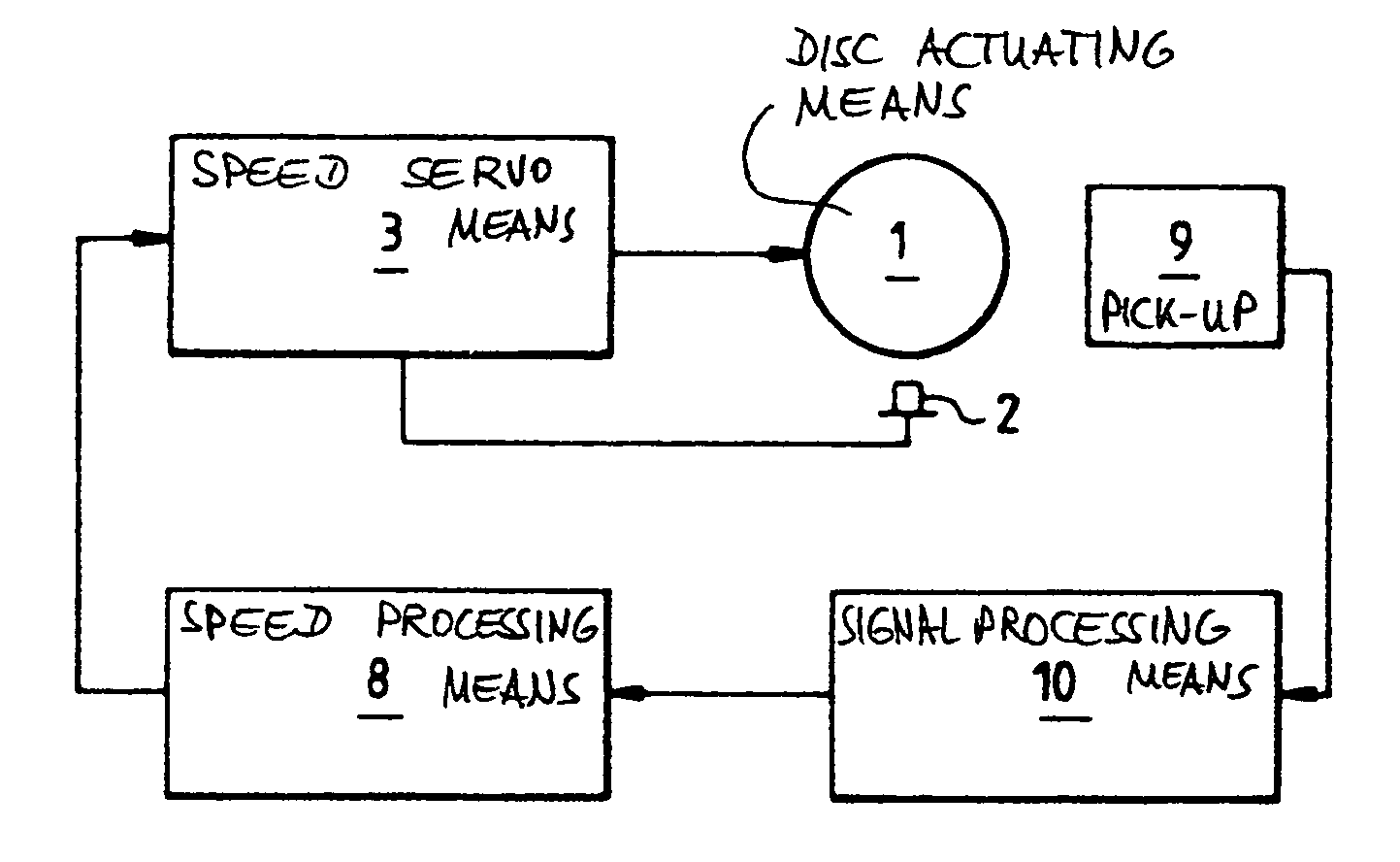
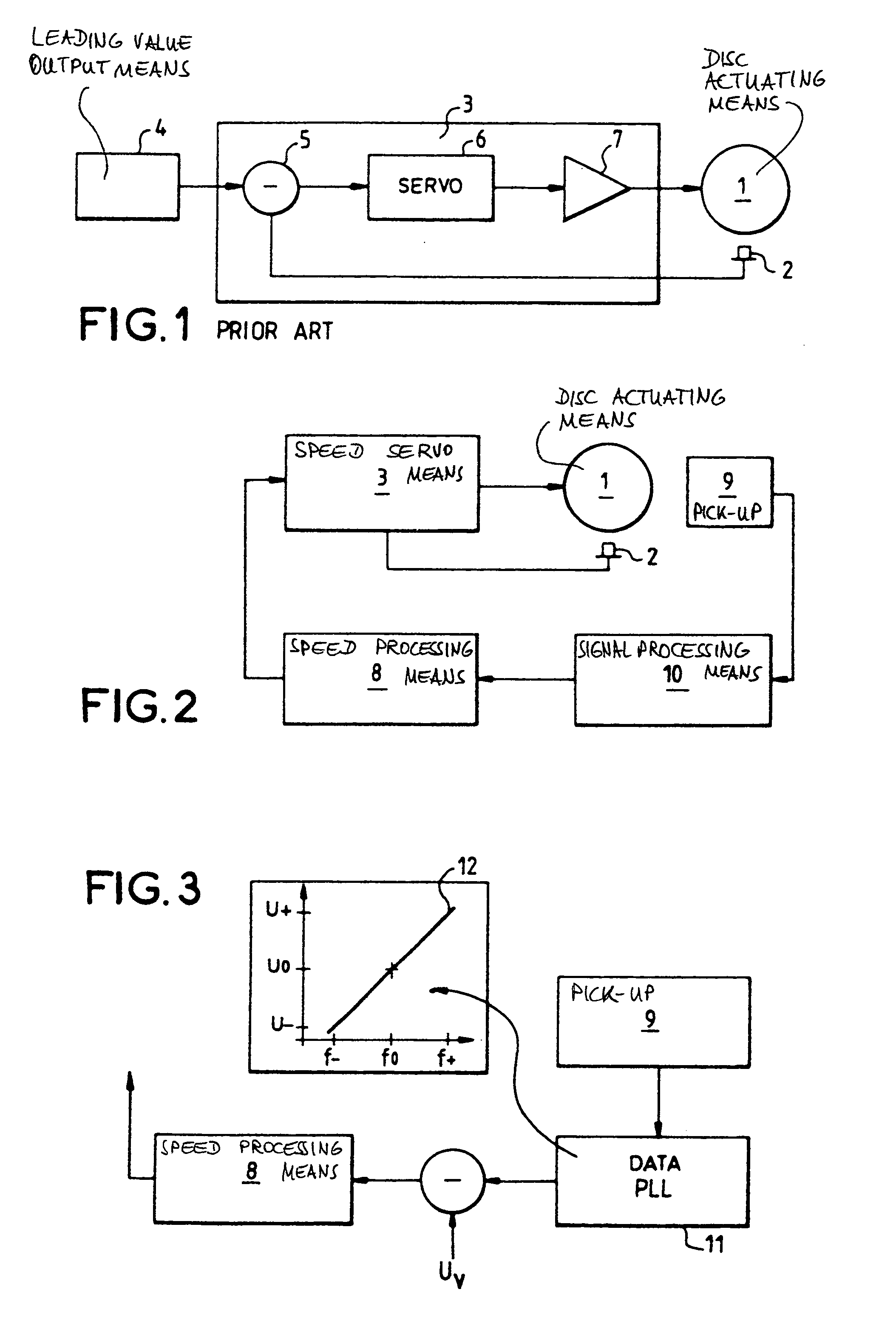
[0014]FIG. 1 shows a schematic representation of known disc actuating means 1 which are used to rotate a disc shaped data carrier (not shown). A frequency generating means 2 measures for example the rotations of a motor shaft (not shown) which rotates in the disc actuating means 1. The frequency generating means 2 thereby generate a frequency signal which has a frequency representative of a rotation speed of the disc, and transmit this to speed servo means 3. A leading value output means 4 generates a determined rotation speed value which is transmitted to the speed servo means 3. The determined rotation speed value corresponds to a desired rotation speed in CAV mode.

[0015]The speed servo means 3 comprises a comparator means 5 which receives both the frequency signal and the determined rotation speed value, compares both inputs and delivers the result of the comparison to a regulating means 6. The regulating means 6 outputs a regulating signal to the disc actuating means 1 through a...


PUM


Abstract

A disc speed control device for use in a disc player and/or recorder having a pick-up for reading/recording data. The device comprises an inner loop which regulates a determined disc rotation speed value received at its input and an outer loop which delivers this speed value depending on a frequency at which data is read by the pick-up. The present invention is particularly useful in multistandard disc drives which need to adjust to different disc speed modes, for example, constant angular velocity, or constant linear velocity.

Description

FIELD OF THE INVENTIION[0001]The invention relates to a playing and / or recording device for a disc shaped information carrier, and more precisely to a disc speed control device.BACKGROUND OF THE INVENTION[0002]A playing and / or recording device for a disc shaped carrier is known to adjust the disc rotation speed depending on the nature of the disc. Typically two modes are used, namely Constant Angular Velocity and Constant Linear Velocity mode.[0003]In CAV mode the disc is rotated at a constant rotation speed. This is for example the case for Compact Disc-ROM devices which are of widespread use as computer peripherals. In a start phase after the disc has been inserted in the CD-ROM player and is ready to be read, a leading value output means generates a determined start rotation speed value. This value is output to speed servo means which regulate disc actuating means such to rotate the disc at the start rotation speed. An instantaneous disc rotation speed may be obtained from a freq...

Claims


Application Information

Patent Timeline
IPC IPC(8): G11B19/28
CPCG11B19/28
Inventor MAHR, PETER
Owner THOMSON LICENSING SA
Why Eureka
Try Eureka