Unlock instant, AI-driven research and patent intelligence for your innovation.

Double lock T-handle assembly

a technology of t-handle and lock, which is applied in the direction of wing knobs, mechanical control devices, keyhole guards, etc., can solve the problems of insufficient secondary locks such as padlocks, difficult to incorporate into existing latch assemblies, and inability to meet the needs of the occupant, etc., and achieves simple and inexpensive design, construction, and operation.

Inactive Publication Date: 2005-10-11
ALLEGIS CORP
View PDF112 Cites 48 Cited by
  • Summary
  • Abstract
  • Description
  • Claims
  • Application Information

AI Technical Summary

Benefits of technology

[0004]An advantage of the invention is to provide a double lock T-handle of relatively simple and inexpensive design, construction, and operation which fulfills the intended purpose without risk of injury to persons and / or damage to property.
[0005]Another advantage of the double lock T-handle is to provide a latching assembly requiring at least two operations prior to the rotation of the handle for separation of a roller cam from a keeper as integral to a structure. The operations required prior to the unlatching of the double lock T-handle include the disengagement of a locking pin from a locking aperture as integral to the Handle through rotation of a locking cylinder. The unlocked handle may then be elevated into a first operational position prior to rotation in either a clockwise or counterclockwise direction. The rotation of the T-handle separates the roller cam from the keeper as integral to a structure to permit movement of a door relative to the structure. Additional steps include the disengagement of a padlock from a padlock hasp, and the retraction of the padlock hasp into the tray or frame to permit elevation of the T-handle to the first elevated operational position.
[0006]Still another advantage of the invention is to provide a double lock T-handle having a shaft integral to a handle where the shaft is engaged to a shaft casing having opposite rotational restriction surfaces which, in turn, are adapted for contact with mating rotational restriction surfaces of a collar to restrict either the clockwise and / or counterclockwise rotation of the handle.
[0007]Still another advantage of the double lock T-handle is to provide a shaft casing having a protruding surface defining first and second rotational restriction surfaces, where the first and second rotational restriction surfaces are adapted for insertion into a slot integral to a collar as engaged to the handle and shaft, during the manipulation of the handle into the non-operational and / or locking position.
[0008]Still another advantage of the present invention is the provision of a double lock T-handle having a padlock hasp which is retractable into a tray following removal of a padlock from the padlock hasp.
[0009]Still another advantage of the present invention is the provision of a double lock T-handle having a locking cylinder which may be manipulated by a key to rotate the locking cylinder having a cam which actuates a pin. The pin may be positioned in a slot or affixed to a pin bracket. The pin may be elevated from the pin bracket or casing through a pin slot or bore for insertion into the pin aperture within the handle to lock the handle in a non-operational position.

Problems solved by technology

Secondary locks such as padlocks are frequently inadequate, absent, and / or difficult to incorporate into an existing latch assembly.

Method used


Image

  • Double lock T-handle assembly
  • Double lock T-handle assembly
  • Double lock T-handle assembly

Examples


Embodiment Construction

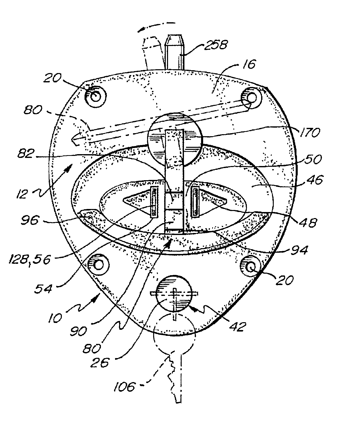
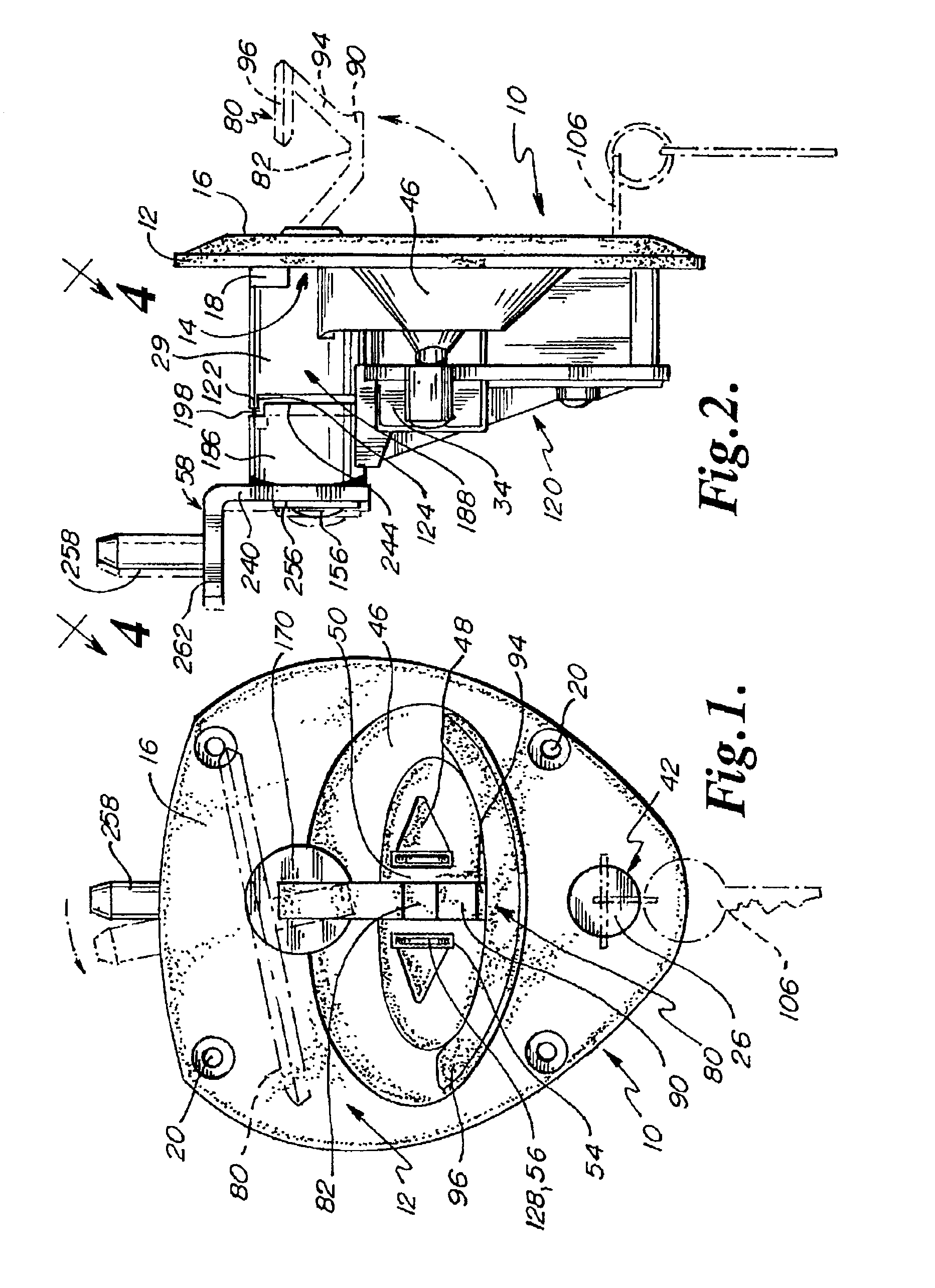
[0037]In general, the double lock T-handle assembly is indicated by the numeral 10. The double lock T-handle assembly 10 is preferably formed of a tray 12. The tray 12, may be stamped, die-cast, or formed of molded plastic, fiberglass, metal, stainless steel, and / or a desired type of composite material. The tray 12 is preferably adapted for positioning within an opening in a door such as a semi tractor access door. The tray 12 has a back side 14 and a front side 16.

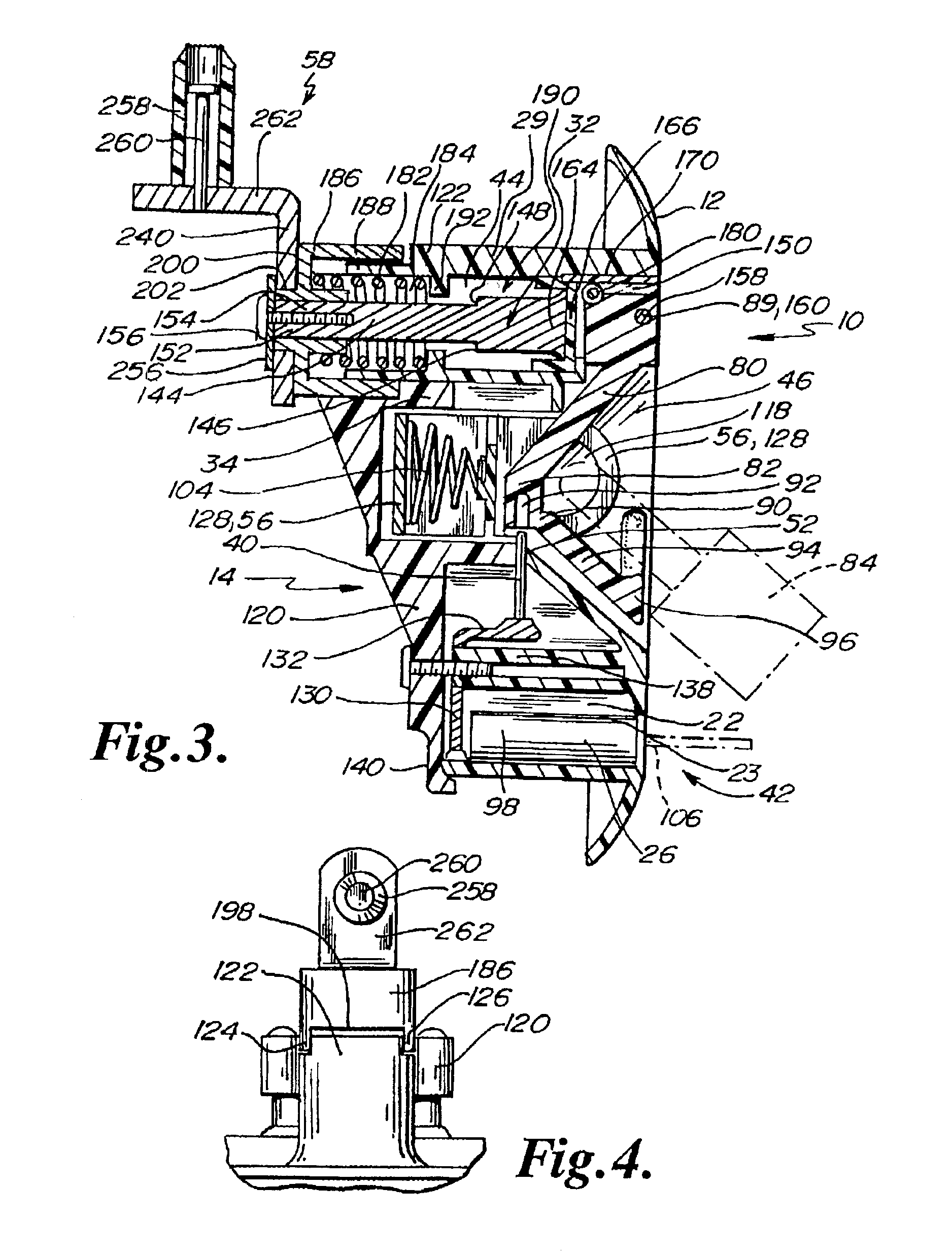
[0038]The back side 14 preferably has a plurality of index pins 18 which function to prevent rotation of the base 12 relative to the door of a vehicle and / or other structure. The tray 12 also preferably includes a plurality of affixation apertures 20 which are adapted to receivingly engage fasteners such as screws to securely position the tray 12 relative to a door of a vehicle. The affixation apertures 20 are preferably regularly spaced about the circumference of the tray 12.

[0039]The back side 14 may be entirely encased...


PUM


Abstract

A double lock T-handle is disclosed having a tray which includes an inwardly dished handle receiving area, a second recessed handle receiving region, and a recessed padlock receiving depression. The tray further includes a lock cylinder casing having a locking cylinder and a shaft cylinder casing having a shaft. The lock cylinder functions as a first lock and a padlock functions as a second lock for the double lock T-handle. The T-handle includes a locking shoulder and a fracturable throat section which deters forced breakage of the T-handle and undesirable opening of a locked door.

Description

CROSS REFERENCE TO RELATED APPLICATIONS[0001]This patent application relates to a double lock T-handle assembly and is a continuation-in-part application which is based upon U.S. application Ser. No. 10 / 014,841 filed Oct. 2, 2001, now U.S. Pat No. 6,532,778, which in turn claims priority to U.S. Provisional Patent Application Ser. No. 60 / 242,591 filed Oct. 23, 2000, the entire contents both of which are incorporated herein by reference in their entireties.BACKGROUND[0002]Latch assemblies with handles have been known. In the past, latch assemblies have been lockable through the use of an internal lock cylinder to prevent the undesirable rotation at the handle. Latch assemblies are frequently manipulated between a locked and / or an unlocked position. In general, the unlocked position is representative of the handle being rotated where the attached door may be opened with one hand. Generally, for a right handed individual the handle is rotated in a clockwise direction for opening of a d...

Claims


Application Information

Patent Timeline
IPC IPC(8): E05B13/00E05B1/00E05B17/00E05B35/12E05B35/00E05B67/00E05B67/38
CPCE05B1/0092E05B13/002E05B17/0062E05B35/12E05B67/383Y10T70/5761Y10T70/577Y10T70/5779
Inventor MOLZER, KLAUSMOLZER, FREDERICK
Owner ALLEGIS CORP