Drilling systems

a drilling system and drilling fluid technology, applied in the direction of chemistry apparatus and processes, wellbore/well accessories, construction, etc., can solve the problems of increasing complexity, affecting drilling efficiency, and halting operations, so as to reduce the density of drilling fluid

Active Publication Date: 2005-10-11
VARCO I P INC
View PDF42 Cites 40 Cited by
  • Summary
  • Abstract
  • Description
  • Claims
  • Application Information

AI Technical Summary

Benefits of technology

[0015]The present invention, in certain aspects, discloses methods for providing a mixture of drilling fluid and beads into a flow of drilling fluid flowing upwardly within a riser, the methods including introducing an initial stream including a mixture of drilling fluid and beads into a hydrocyclone; processing the initial stream with the hydrocyclone producing a first stream and a second stream, the first stream containing drilling fluid and beads and the second stream containing drilling fluid, and feeding the first stream to shale shaker apparatus or to centrifugal liquid / liquid separator apparatus producing a primary stream and a secondary stream, the primary stream including beads and drilling fluid, wherein the second stream is drilling fluid substantially free of beads, wherein the first stream is, by volume, between 10% to 30% beads and 70% to 90% drilling fluid, wherein in the aspect including shale shaker apparatus it includes at least one shale shaker having vibrating apparatus able to produce forces of at least 5.5 G force, wherein the primary stream is, by volume, about 50% beads and about 50% drilling fluid, and feeding the primary stream into a flow of drilling fluid flowing upwardly within a riser to reduce density of said drilling fluid flowing upwardly within the riser.
[0017]The present invention discloses, in at least certain aspects, a method for providing a mixture of drilling fluid and beads into a flow of drilling fluid flowing upwardly within a riser, the method including continuously introducing an initial stream including a mixture of drilling fluid and beads into hydrocyclone apparatus; processing the initial stream with the hydrocyclone apparatus producing a first stream and a second stream, the first stream containing drilling fluid and beads and the second stream containing drilling fluid; continuously producing the first stream; and continuously feeding the first stream into the riser to continuously reduce density of drilling fluid therein.

Problems solved by technology

When drilling in deep water or ultra deep water this is further complicated because of the pressure on the sea floor by the water above it.
When the mud density is insufficient, the gases or fluids in the borehole can cause the mud to decrease in density and become so light that a blowout occurs which can bring drilling operations to a halt and cause significant damage and injury.
In certain methods, to maintain a safe margin, the column of drilling mud in the annular space around the drill stem is of sufficient weight and density to produce a high enough pressure to limit risk to near zero in normal drilling conditions, but this can slow the drilling process.
Underbalanced drilling is sued in some prior art methods to increase the drilling rate.
The need to provide a high density mud in a well bore that starts several thousand feet below sea level in deep water or ultra deep water drilling can present a variety of problems.
Pumps have been employed in certain prior art methods near the seabed for pumping out the returning mud and cuttings from the seabed above the BOP's and to the surface using a return line that is separate from the typical subsea riser system, a system which is expensive to install, requiring separate lines, expensive to maintain and very expensive to run.
This hydrostatic pressure gradient line traverses across the pore pressure gradient and fracture pressure gradient over a short vertical distance, which can result in having to set numerous casing strings.
The setting of casing strings is expensive in terms of time and equipment.
This is not safe, environmentally practical or economically viable.
This requires no major subsea mechanical equipment, but it has some limitations.
Since gas is compressible, the depth at which it may be utilized is limited and extensive surface equipment may be required.
Also, because the gas expands as the drilling fluid reaches the surface, surface flow rates can be excessive.
Sea floor pump systems provide the flexibility needed to handle drilling situations, but they have the disadvantage of high cost and reliability problems associated with keeping complex pumping systems operating reliably on the sea floor.

Method used


Image

  • Drilling systems
  • Drilling systems
  • Drilling systems

Examples


Embodiment Construction

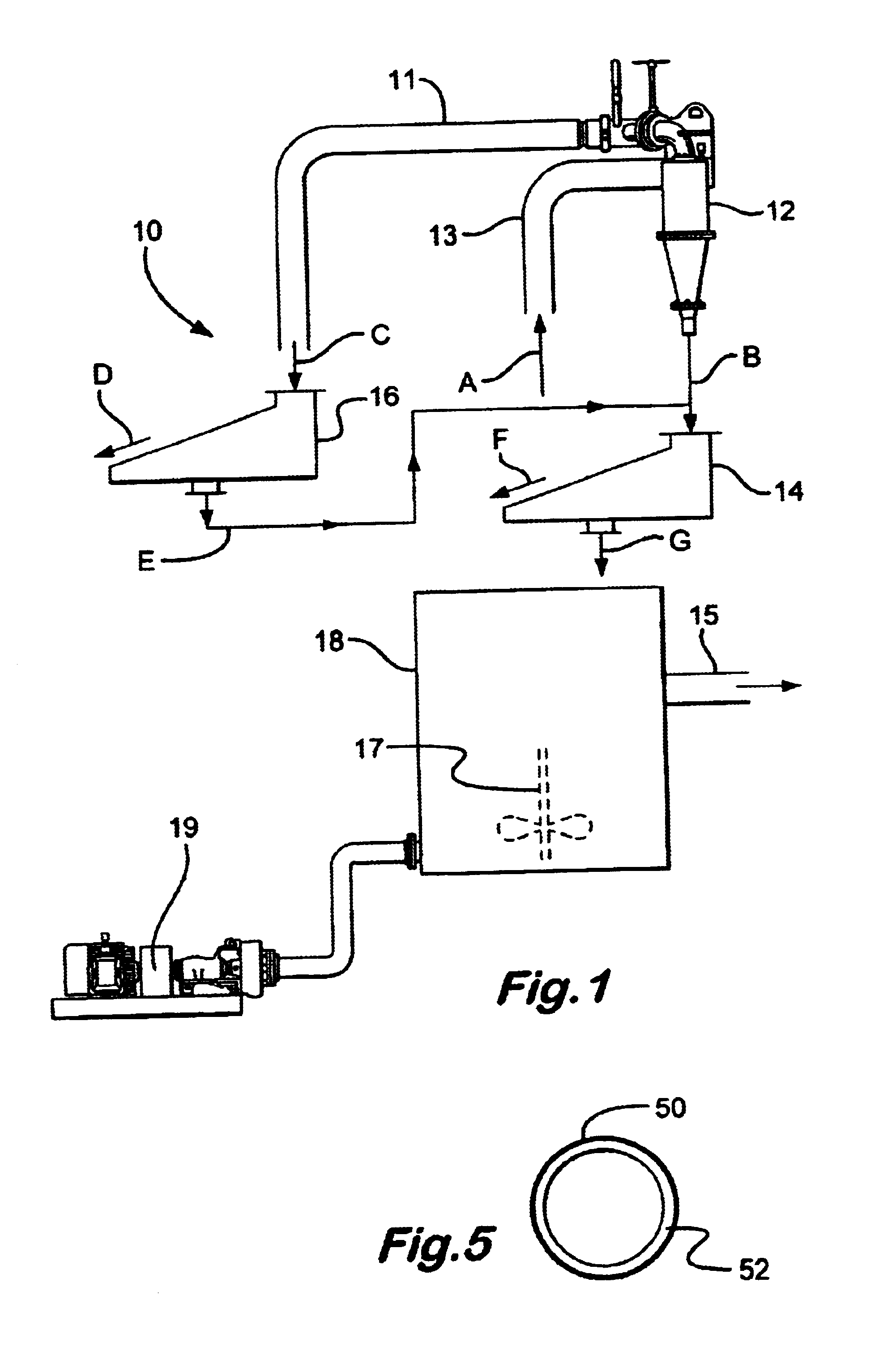
[0029]Referring now to FIG. 1, a system 10 according to the present invention has a hydrocyclone 12 which, in one particular aspect is a Brandt 12″ high pressure cone hydrocyclone from Brandt / Varco Company with a high pressure cone unit. A mixture of drilling fluid and beads is introduced in a line A into the hydrocyclone. The beads may be any known beads used to reduce density of drilling fluid or any suitable bead, hollow or solid, of any desirable shape. e.g., but not limited to spherical, generally cylindrical, or generally cylindrical with rounded ends. In one particular aspect, the mixture in the line A, by volume, is about 50% beads and about 50% drilling fluid. In one particular aspect the beads are hollow glass bodies with a main body that is generally cylindrical in shape, with rounded ends, a length of about 3 / 16 inch, and a diameter of about ⅛ inch. Within the hydrocyclone 12 the beads are separated and move upwardly within the hydrocyclone 12 and are expelled, with some...


PUM


Abstract

Systems and methods for providing a mixture of drilling fluid and beads into a flow of drilling fluid, e.g., flowing in a conduit or flowing upwardly within an annulus of a riser, the method in certain aspects including: introducing an initial stream including a mixture of drilling fluid and beads into a hydrocyclone; processing the initial stream with the hydrocyclone producing a first stream and a second stream, the first stream containing drilling fluid and beads and the second stream containing drilling fluid; and feeding the first stream to shale shaker apparatus and / or to centrifugal liquid / liquid separator apparatus producing a primary stream and a secondary stream, the primary stream including beads and drilling fluid; and feeding the primary stream into the conduit or into an annulus of the riser.

Description

BACKGROUND OF THE INVENTION[0001]1. Field of the Invention[0002]The present invention, in at least certain embodiments, is directed to methods for efficiently recovering beads or spheres from a dual density drilling fluid; to systems useful in such recovery; and to dual gradient drilling systems and processes that use such bead or sphere recovery methods.[0003]2. Description of Related Art[0004]The prior art discloses a variety of systems for providing drilling fluids (often referred to as “drilling mud”) for oil and gas drilling applications and methods and apparatus for varying the density of mud in deep water oil and gas drilling operations. In many such methods drilling mud drives drill bits, maintains hydrostatic pressure, and carries away particulate matter, debris, and drilled cuttings. In many methods drilling mud is pumped down the drill pipe and provides the fluid driving force for a drill bit and then it flows back up from the bit along the periphery of the drill pipe in ...

Claims


Application Information

Patent Timeline
Patent Type & Authority Patents(United States)
IPC IPC(8): E21B21/00E21B21/06
CPCE21B21/001E21B21/065E21B2021/006E21B21/085
Inventor SEYFFERT, KENNETH W.
Owner VARCO I P INC
Why Eureka
Try Eureka