Device-specific color intensity settings and sub-pixel geometry

Inactive Publication Date: 2005-10-11
ADOBE INC
View PDF12 Cites 36 Cited by
  • Summary
  • Abstract
  • Description
  • Claims
  • Application Information

AI Technical Summary

Benefits of technology

[0013]Advantages that can be seen in implementations of the invention include one or more of the following. A user can determine a set of device-specific pixel input values that will cause a display system to display a corresponding set of target visual output intensities relative to the output display device such that fine structure monochrome images displayed appear to the user to be optimal for the output display device. A user can select a device-specific sub-pixel geometry for all pixels of the output display device where each

Problems solved by technology

The human eye does not ‘see’ closely spaced colors individually, and as such, cannot distinguish the individual color components.
Unfortunately, device-specific pixel information that look good when used in displaying the text on one type of output d

Method used


Image

  • Device-specific color intensity settings and sub-pixel geometry
  • Device-specific color intensity settings and sub-pixel geometry
  • Device-specific color intensity settings and sub-pixel geometry

Examples


Embodiment Construction

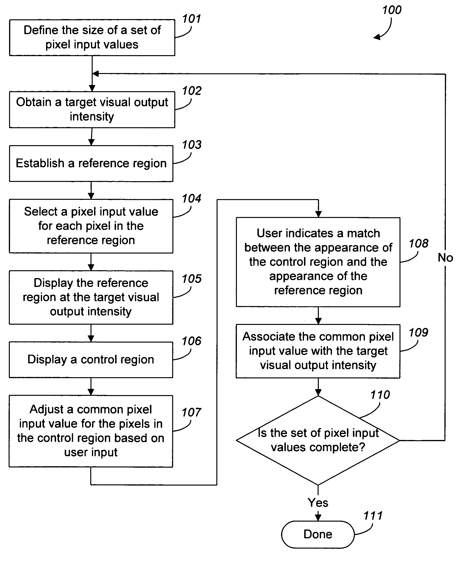
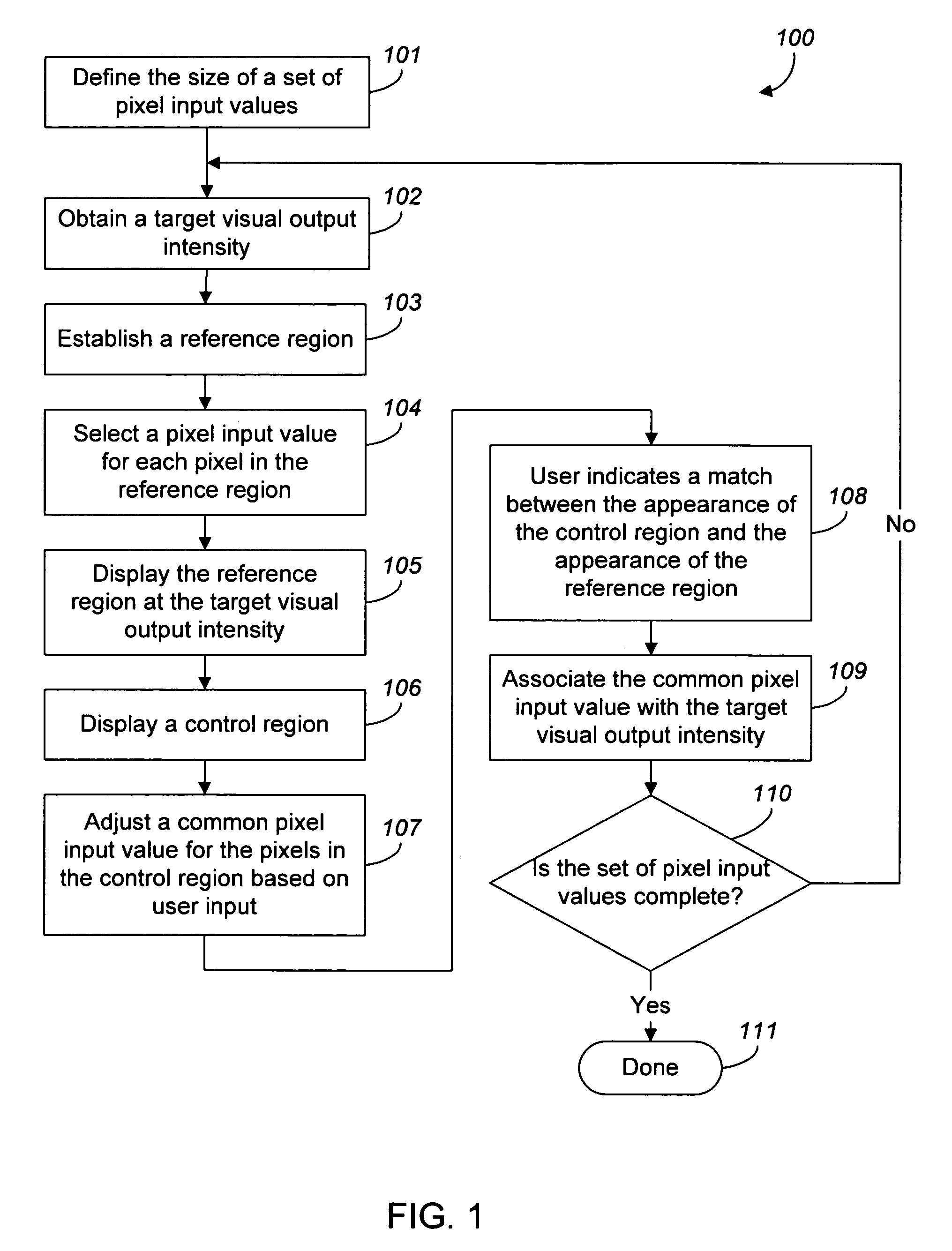
[0029]FIG. 1 is a flow diagram of a process 100 for determining a set of device-specific pixel input values that will cause a display system to display a corresponding set of target visual output intensities relative to an output display device.

[0030]The process 100 first obtains a numeric value defining the size of the set of pixel input values for which the corresponding visual output intensities are known (step 101) for the output display device 400. In one implementation, the user is prompted for the numeric value. In another implementation, the process 100 obtains a pre-programmed numeric value. The process 100 then obtains a target visual output intensity (step 102). In one implementation, the user is prompted for the target visual output intensity.

[0031]The process 100 then establishes a reference region 402 (step 103) defined by a plurality of reference pixels in the output display device 400, as shown in FIG. 4. The process 100 selects a pixel input value for each of the re...


PUM


Abstract

A method for determining device-specific information for pixels to obtain an optimal display of fine structure monochrome images on an output display device, the method comprising determining a set of device-specific pixel input values that will cause the display system to display a corresponding set of target visual output intensities relative to the output display device, and determining a device-specific sub-pixel geometry for all the pixels of the output display device. Displaying for each of the pixels a selected visual output intensity relative to the output display device at a sub-pixel position according to a corresponding pixel input value will cause an optimal display of fine structure monochrome images to be displayed on the output display device.

Description

BACKGROUND OF THE INVENTION[0001]The present invention relates to device-specific information for pixels.[0002]Color in computer graphics is defined in terms of “color spaces”, which are related to real or imaginary color display devices such as monitors, liquid crystal displays and color printers. Various color spaces are used to represent color on computers. Each image is associated with a color space which defines colors according to a combination of properties. For example, in a RGB (Red, Green, Blue) color space, each color is represented by a combination of red, green and blue components. In a CMYK (Cyan, Magenta, Yellow, Black) color space, each color is represented as a combination of cyan, magenta, yellow and black.[0003]An output display device such as a computer monitor, liquid crystal display (LCD) or printer is capable of reproducing a limited range of colors. An output display device's “color gamut” is the set of colors that the output display device is capable of repr...

Claims


Application Information

Patent Timeline
IPC IPC(8): G09G5/02
CPCG09G3/2003G09G2300/0452G09G2320/0242G09G2340/0457
Inventor DOWLING, TERENCE S.HALL, JEREMY A.
Owner ADOBE INC
Why Eureka
Try Eureka