Image forming apparatus

a technology of image forming and forming tubes, applied in the direction of electrographic process apparatus, instruments, optics, etc., can solve the problems of difficult flexing and movement of recording media, inability to run at the same speed of transfer belts, and inability to always maintain the constant interpage gap, so as to achieve the effect of minimizing color shi

Active Publication Date: 2009-04-02
OKI ELECTRIC IND CO LTD
View PDF17 Cites 2 Cited by
  • Summary
  • Abstract
  • Description
  • Claims
  • Application Information

AI Technical Summary

Benefits of technology

[0008]An object of the present invention is to provide an image forming apparatus in which color shift is minimized even when printing is performed on a thick, rigid recording medium.

Problems solved by technology

However, the transfer belt may not run at the same speed as the paper transporting mechanism, in which case, the interpage gap may not be always constant.
This is particularly true if the recording medium is thick and rigid so that the recording medium is difficult to flex and moves relative to the transfer belt.
This causes positional errors of the recording medium and therefore color shift in a printed image.

Method used


Image

  • Image forming apparatus
  • Image forming apparatus
  • Image forming apparatus

Examples


first embodiment

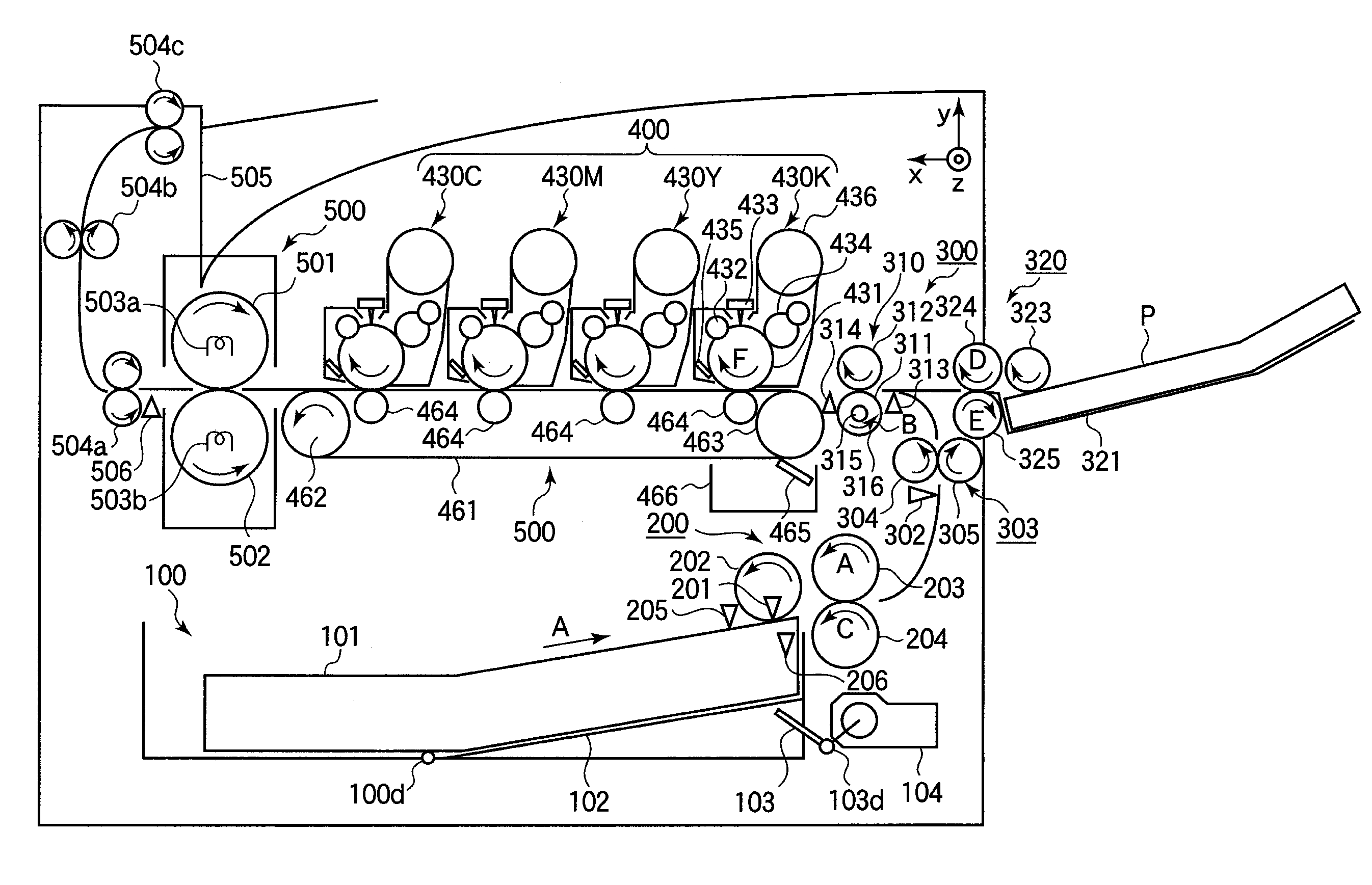
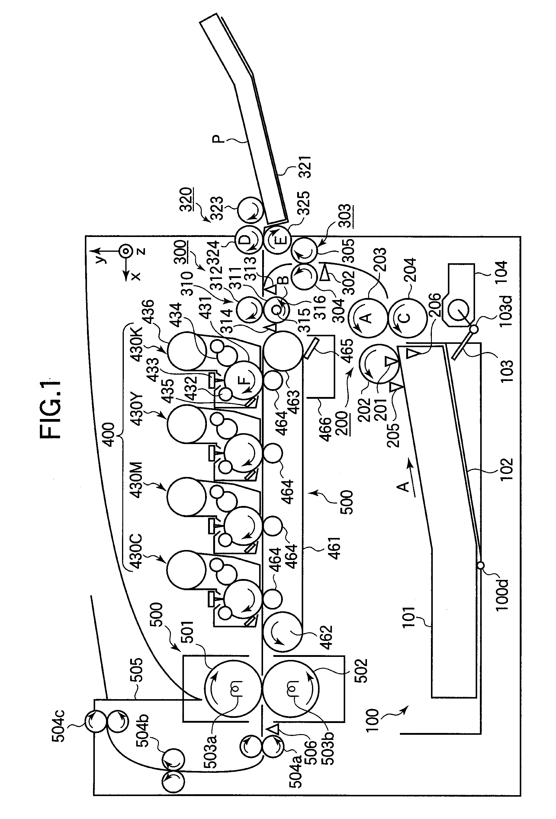
[0024]FIG. 1 illustrates the configuration of an image forming apparatus of the invention. The image forming apparatus includes a paper tray 100, a paper feeding section 200, a paper transporting section 300, a multi purpose tray (MPT) 320, a color image forming section 400, a transfer section 460, and a fixing section 500.

[0025]The paper tray 100 is a rectangular, and includes a platform 102 disposed at its bottom. The paper tray 100 is detachably attached to the image forming apparatus, and holds a stack of recording medium such as paper 101 or OHP sheet (i.e., transparencies). The platform 102 is pivotally mounted to a shaft 100d. A lift-up lever 103 is disposed at an exit of the paper tray 100, and is pivotal about a shaft 103d. When the paper tray 100 is attached to the image forming apparatus, the shaft 103d is detachably coupled to a motor 104. The motor 104 drives the shaft 103d in rotation so that the lift-up lever 103 pivots about the shaft 100d upward. As a result, a stac...

second embodiment

[0097]FIG. 16 illustrates an image forming apparatus of a second embodiment. The configuration of the image forming apparatus of the second embodiment is identical with that of the first embodiment, and differs only in interpage distance. Thus, the detailed description of the configuration of the image forming apparatus is omitted.

[0098]When continuous printing is performed on paper having a thickness larger than a predetermined thickness, the image forming apparatus is controlled to transport the pages with an interpage distance such that LF>Lall, where Lall is a distance between the nip at the most upstream process unit 430K and the nip at the most downstream process unit 430C. If thick paper having a basic weight equal to or more than 120 g / m2 is used, the interpage distance LF is as follows:

LF>Lall=L1+L2+L3

LF>L1+L2+L3  (2)

[0099]In other words, the interpage distance LF between the trailing edge Pe(n) of page P(n) and the leading edge Ps(n+1) of page P(n+1) is larger than t...


PUM


Abstract

A controller controls transportation of the recording medium such that a first distance between a trailing edge of an image area of a preceding page of the two successive pages and a leading edge of an image area of a following page is equal to or longer than a second distance between the nip at a most upstream one of the image forming sections and the nip at a most downstream one of the image forming sections. Control may also be performed such that a first distance between a trailing edge of a preceding page of the two successive pages and a leading edge of a following page is equal to or longer than a second distance between the nip at a most upstream one of the plurality of image forming sections and the nip at a most downstream one of the plurality of image forming sections.

Description

BACKGROUND OF THE INVENTION[0001]1. Field of the Invention[0002]The present invention relates generally to an image forming apparatus that prints an image on a recording medium.[0003]2. Description of the Related Art[0004]A conventional image forming apparatus such as a copying machine, a printer, or a facsimile machine employs an electrophotographic process. A charging device uniformly charges the surface of a photoconductive body. An exposing device such as a laser scanner or an LED head illuminates the charged surface to write an electrostatic latent image on the photoconductive body. A developing device supplies toner to the electrostatic latent image to form a toner image. The toner image is transferred onto a recording medium such as paper or a film directly or indirectly via an intermediate transfer system. The recording medium is then advanced to a fixing device where the toner image is fused to the recording medium.[0005]The image forming apparatus includes a feed roller th...

Claims


Application Information

Patent Timeline
Patent Type & Authority Applications(United States)
IPC IPC(8): G03G15/00
CPCG03G15/0131G03G2215/00556G03G15/6567G03G2215/0119G03G15/6564G03G2215/00721
Inventor UDAGAWA, HIROSHI
Owner OKI ELECTRIC IND CO LTD
Why Eureka
Try Eureka