
Intelligent cooling fan

a cooling fan and intelligent technology, applied in the field of intelligent cooling fans, can solve the problems of permanent damage to the system, no standard design or protocol available to control cooling fans produced by different manufacturers, and add to the cost of the overall system utilizing the cooling fan(s)

Inactive Publication Date: 2005-10-11
MINEBEAMITSUMI INC
View PDF44 Cites 63 Cited by
  • Summary
  • Abstract
  • Description
  • Claims
  • Application Information

AI Technical Summary

Problems solved by technology

The inability to remove excessive heat from electronic systems may lead to permanent damage of the system.
Although these functionalities exist in some cooling fans today, there is no standard design or protocol that is available to control cooling fans produced by different manufacturers.
The design and manufacture of PCAs and controller cards involve a great deal of engineering time and resources, which ultimately add to the cost of the overall system utilizing the cooling fan(s).
Designing cooling solutions for new systems is also a time-consuming process for the thermal design engineer.
The multiple iterations of installing sample fans in a system, determining the adequate fan speeds and power required, and testing the fans in the system, for example, are costly and inefficient.
However, having to install a voltage regulating power supply adds additional complexity and cost to the overall system as well.

Method used


Image

  • Intelligent cooling fan
  • Intelligent cooling fan
  • Intelligent cooling fan

Examples


Embodiment Construction

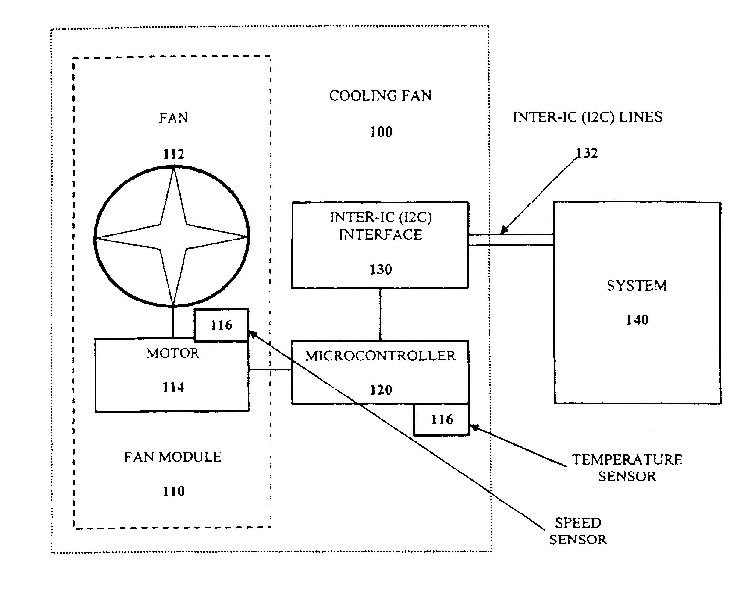
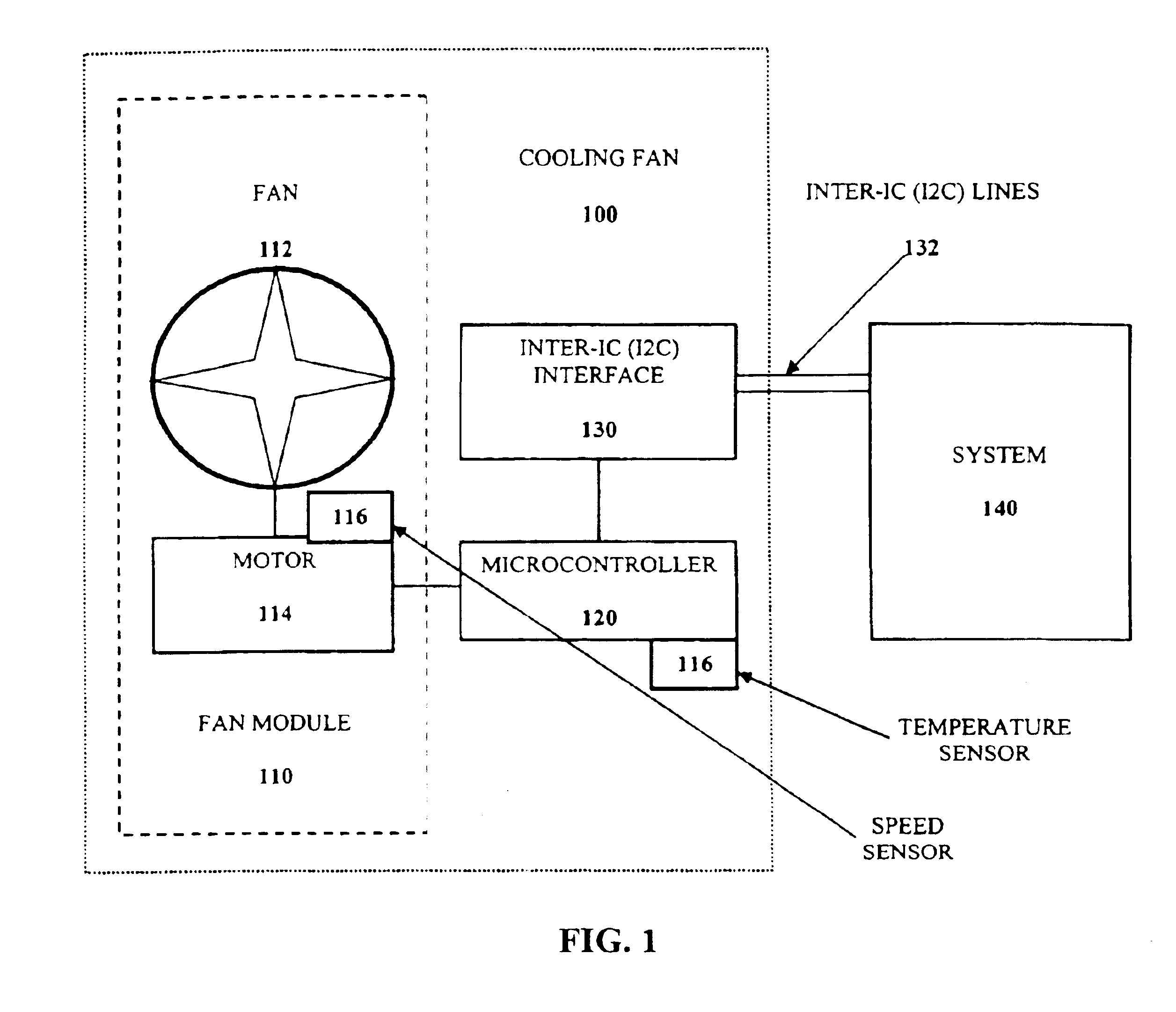
[0019]FIG. 1 illustrates a cooling fan solution according to an embodiment of the present invention. The cooling fan 100 includes a fan module 110, which has a fan 112 (including fan blades) and a motor 114 rotatably coupled to the fan 112 to drive the fan 112. A microcontroller 120, such as an 18-pin PIC16C717 microcontroller device manufactured by Microchip Technology, Inc., is in direct communication with the fan module 110, and specifically, the motor 114. Any suitable microcontroller or processor may be utilized, though. The microcontroller 120 is preferably fixed internally within the cooling fan 100.

[0020]A bus interface, such as the Inter-IC (I2C) (“I2C-Bus Specification”, Version 2.1, January 2000, from Philips Semiconductors) bus interface 130 is in communication with the microcontroller 120. The bus interface 130 facilitates transfer of data to and from the microcontroller 120. The bus interface 130 may be interconnected by bus lines 132, such as I2C bus lines, to a syste...


PUM


Abstract

A cooling fan including a fan module, a microcontroller, and a bus interface. The microcontroller is coupled to the fan module and is capable of adjusting a speed of the cooling fan based on a status of a second cooling fan and adjusting the speed of the cooling fan based on a temperature detected. The bus interface is in communication with the microcontroller, the second cooling fan, and the system to receive and output data.

Description

RELATED APPLICATIONS[0001]This is a continuation of U.S. patent application Ser. No. 10 / 175,875, filed Jun. 20, 2002, now U.S. Pat. No. 6,725,132.BACKGROUND OF THE INVENTION[0002]1. Technical Field[0003]The present invention relates to cooling fans. More particularly, the present invention relates to intelligent cooling fans for use in electronic systems and for designing cooling solutions for electronic systems.[0004]2. Discussion of the Related Art[0005]In electronic systems, such as computer systems, cooling fans play an important role in maintaining their operational capabilities. The inability to remove excessive heat from electronic systems may lead to permanent damage of the system. Because of the complexity of existing electronic systems, cooling fans having added functionalities other than just providing cooling air, such as the ability to control the speed of a fan, the ability to monitor a tachometer pulse on a fan to determine instantaneous fan speed, and the ability to ...

Claims


Application Information

Patent Timeline
Patent Type & Authority Patents(United States)
IPC IPC(8): G05D23/19
CPCG05D23/1902
Inventor FRANKEL, SCOTTMARTIN, PETERHARDT, ERIC
Owner MINEBEAMITSUMI INC
Learn More