Tool with rotatable handle grip

a technology of rotatable handle and tool, which is applied in the field of tools with rotatable handle grips, can solve the problems of user's hands being in an unergonomic position, and achieve the effect of adding energy to the thrust and reducing weigh

Inactive Publication Date: 2005-10-18
HIXON WILLIAM K
View PDF17 Cites 6 Cited by
  • Summary
  • Abstract
  • Description
  • Claims
  • Application Information

AI Technical Summary

Benefits of technology

[0013]The present invention provides a hand held tool, such as a plant harvesting device, that has a rotatable handle grip. The rotatable handle grip provides the tool user with the convenience and advantage of adjusting the orientation of the handle grip, thus allowing the user to hold the tool in an ergonomically favorable or otherwise desirable position.
[0015]The present invention may also include at least one cutting blade interposed between adjacent tines. The invention may also have a bar coupled with the at least one cutting blade, and may also have a reinforcing rod coupled with the bar and with the second end of at least one tine. The bar can stabilize the cutting blade, and also can absorb stress received by the cutting blade during use. Additionally, the bar can support or hold plant material which has been severed by the cutting blade.
[0021]In another embodiment, the device is an attachment for a standard pitchfork. The device being comprised of two main pieces, a top bar and a bottom bar, which includes the pusher, collector, and clamping piece. The bottom bar has affixed to it the required number of cutting means as well as the fastening devices. The top bar is formed with a 90 degree angle iron to both clamp the unit together and to provide the pushing, collecting and snapping effect (as weed bends back it hits the top angle iron and tends to snap). It also has a little weight which adds energy to the thrust. The bottom bar, which is comprised of the bar and cutting sections, is clamped to the fork on the tines. It is positioned at the bend to allow the sharpened sections to protrude in a downward fashion. The angle of attack can be determined by the operator, by moving the handle up or down. This device cuts off plants in one thrust and is particularly useful for harvesting beans. The bean plants are snapped off by the thrust. The cutting edge of the sections must be against the tines of the fork and the plant can be captured from the sharp edge of the section as well as in the crotch between the sections. The device is used to harvest vegetation and does so by the forward thrusting of the pitchfork. The tines of the pitchfork slide along the ground and the points of the times do not dig into the ground. By rocking the pitchfork up and down the angle of attack of the pitchfork tines is adjusted so that they scoot along the ground rather than dig in. The triangular blades can be moved backward and forward to achieve the right angle for the particular job. The tines of the pitchfork slide along the ground, plants are captured by the triangular blades of the cutters. The plants are captured at ground level. As this device is thrust forward, a mat of harvested plants accumulates and builds up on the angle iron. Periodically the stack of plants which builds up on the angle iron is removed to clear the device.

Problems solved by technology

Unfortunately, such tools often force the user to have their hands in an unergonomic position.

Method used


Image

  • Tool with rotatable handle grip
  • Tool with rotatable handle grip
  • Tool with rotatable handle grip

Examples


Embodiment Construction

[0029]While the invention is susceptible of various modifications and alternative constructions, certain illustrated embodiments thereof have been shown in the drawings and will be described below in detail. It should be understood, however, that there is no intention to limit the invention to the specific form disclosed, but, on the contrary, the invention is to cover all modifications, alternative constructions, and equivalents falling within the spirit and scope of the invention as defined in the claims.

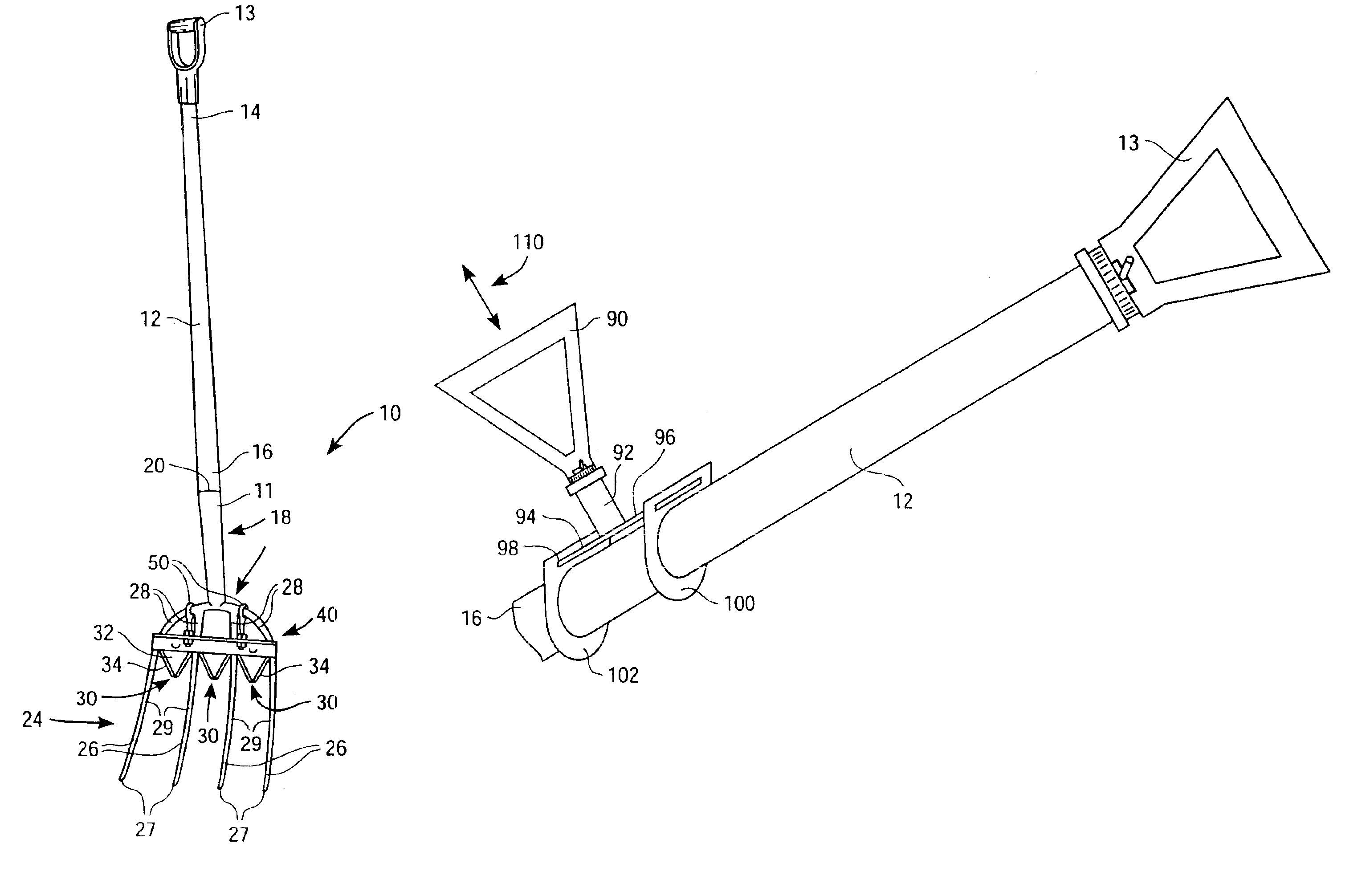
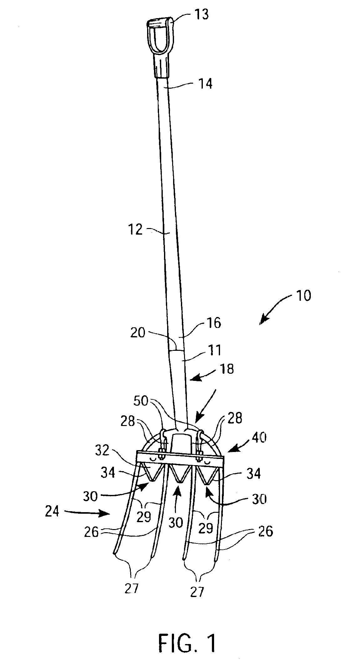
[0030]The present invention provides a handle grip for a hand tool, such as a plant harvesting device. The preferred embodiment of the present invention is shown in FIG. 1. FIG. 1 shows the plant harvesting device 10 comprising an elongated handle 12 attaching to a working end, such as a fork 11. The elongated handle 12 has a first end 14 and a second end 16. The handle 12 attaches to the fork 11 through a handle attachment means 18. This handle attachment means 18 can be through ...


PUM


Abstract

A tool having a rotatable handle grip includes an elongated handle having a first end and second end, wherein a handle grip is rotatably coupled with the first end, and a working end is coupled with the second end. The working end may include a plurality of spaced tines with the prongs having points, wherein at least one cutting blade is coupled to the device between adjacent tines allowing a user to slide the tines of the fork along the ground surface, thereby using the blade to harvest vegetation. Additionally, the working end allows a stack of cut vegetation to accumulate on the device to be carried and placed in a preferred location or container.

Description

CROSS REFERENCES TO RELATED APPLICATIONS[0001]This application is a continuation of U.S. patent application Ser. No. 10 / 101,818 filed on Mar. 19, 2002, now U.S. Pat. No. 6,796,383, which is a continuation-in-part of U.S. patent application Ser. No. 09 / 537,898, filed Mar. 28, 2000, now U.S. Pat. No. 6,401,833, the full disclosures of which are incorporated herein by reference.BACKGROUND OF THE INVENTION[0002]1. Field of the Invention[0003]The present invention generally relates to tools having handle grips, and more particularly to cultivating or harvesting tools having rotatable handle grips.[0004]2. Background Information[0005]Hand held tools are used to perform a wide variety of functions. For example, these implements are commonly used in outdoor applications, and particularly in the fields of farming, landscaping, digging, excavating, gardening, and cultivation. Unfortunately, such tools often force the user to have their hands in an unergonomic position. Examples of hand held t...

Claims


Application Information

Patent Timeline
Patent Type & Authority Patents(United States)
IPC IPC(8): A01D11/06A01D11/00
CPCA01D11/06
Inventor HIXON, WILLIAM K.
Owner HIXON WILLIAM K
Why Eureka
Try Eureka