Merchandise display

a display and pusher mechanism technology, applied in the field of displays, can solve the problems of not providing optimal viewing of the product, not ideal “fronting” the product, and high construction cost, and achieve the effects of convenient stacking assembly, convenient retraction for further stocking, and mechanical simplicity

Inactive Publication Date: 2005-10-18
EXOTIC RUBBER & PLASTICS OF MINNESOTA
View PDF47 Cites 82 Cited by
  • Summary
  • Abstract
  • Description
  • Claims
  • Application Information

AI Technical Summary

Benefits of technology

[0008]A feature and advantage of particular embodiments of the invention is that the shelves may be formed from plastic by extrusion and the extruded shelves assemble, stack, and lock together in a cascade arrangement. This provides great economy and ease in manufacturing of a highly functional and effective display.
[0020]A feature and advantage of particular embodiments of the invention is that the lower base, the back side, the front wall, the top, may all be integral with one another. This provides for ease of manufacture and also provides for ease of assembly and cleaning if necessary.

Problems solved by technology

These are not ideal in that they are expensive to construct, do not provide optimal viewing of the product, do not ideally “front” the product, and do not generally present a highly attractive display.
This presents a loss control issue in that thieves are known to quickly grab a great quantity of DVD's or CD's and then run out of the store.
The known displays that provide a fronting feature generally require a rather complex mechanism for pushing the items forward to the front of the display or utilize separate removable pusher components which can be misplaced and can increase manufacturing costs.
These displays are not particularly aesthetically appealing particularly when the display is empty.
Some display systems utilize gravity which typically does not efficiently utilize the display case area and does not reliably front the product.

Method used


Image

  • Merchandise display
  • Merchandise display
  • Merchandise display

Examples


Embodiment Construction

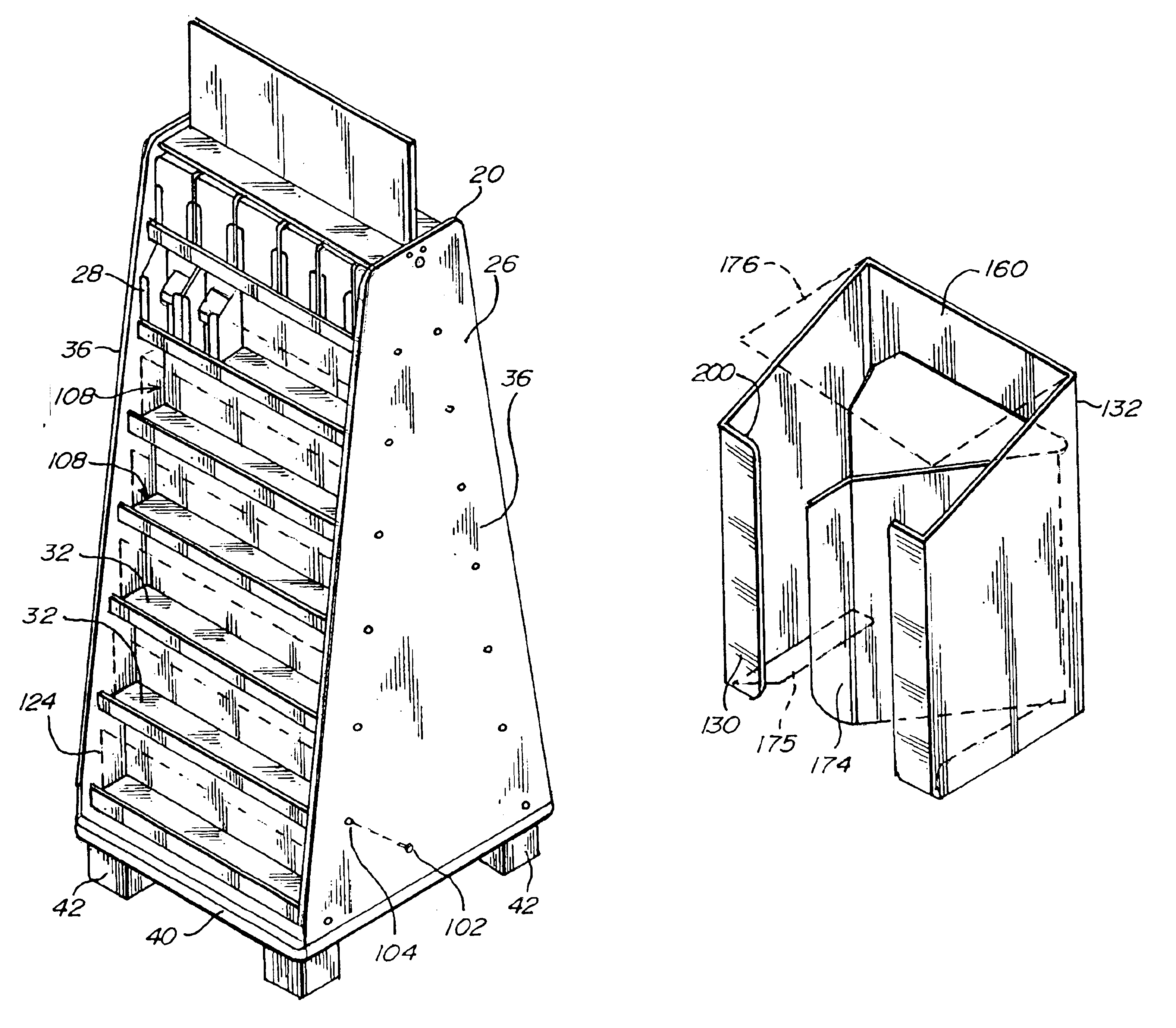
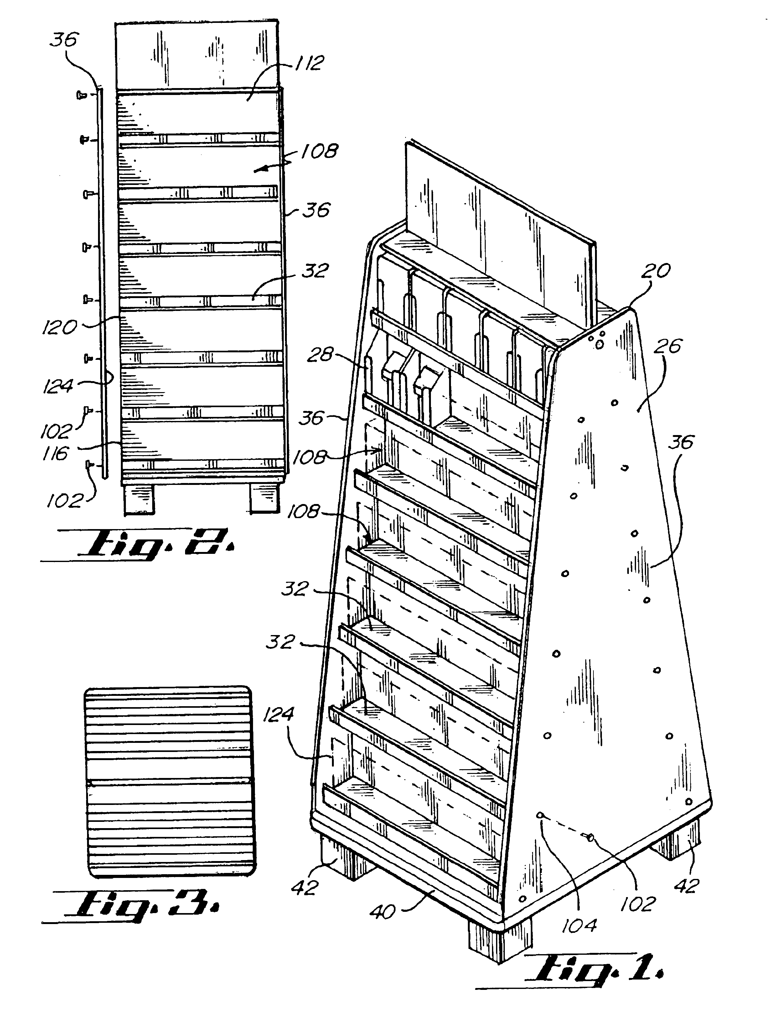
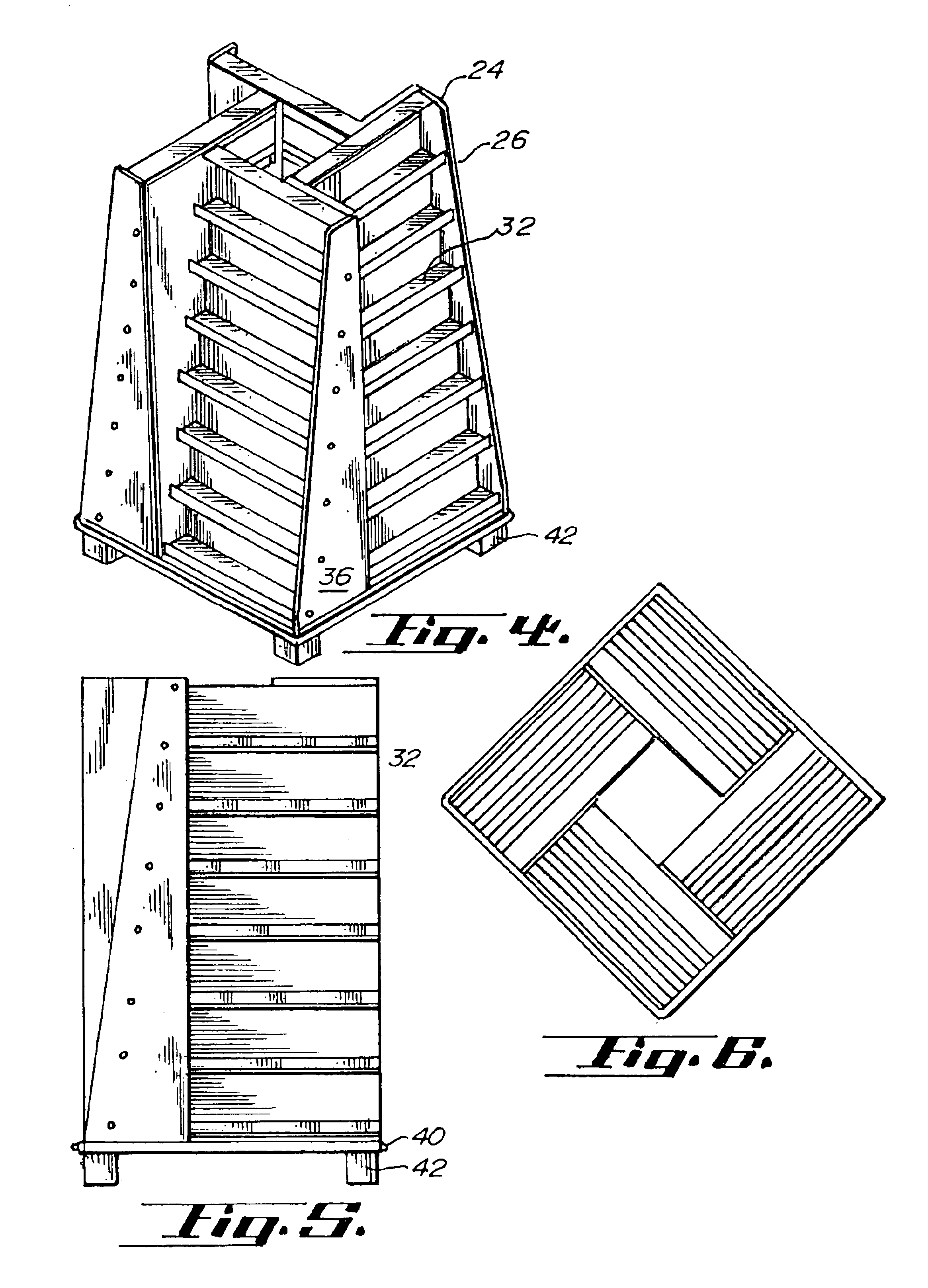
[0035]FIGS. 1-5 illustrate two configurations of merchandise displays 20, 24 in accordance with the invention for holding groupings 22 of individual uniform sized product pieces 23. These embodiments principally comprise a display rack 26 and pocket modules 28 retained therein. The display rack is comprised of a plurality of supports, configured as shelves 32, end panels 36, a base 40 and feet 42.

[0036]Referring to FIGS. 7, 8 and 9, details of the shelves are illustrated. FIG. 7 in particular shows two shelves 50 which are assembled together in a cascading fashion as illustrated in FIGS. 1 and 4. The upper shelf is offset slightly backward from the lower shelf. These shelves each are comprised of an integral base portion 54, an integral back side portion 56, an integral top portion 58, and an integral front portion 60. The shelves as illustrated are preferably formed of a plastic extrusion. Adjacent to the top portion and back side portion is a boss (70) defining an aperture 72 conf...


PUM

PropertyMeasurementUnit
thicknessaaaaaaaaaa
thicknessaaaaaaaaaa
thicknessaaaaaaaaaa

Abstract

A modular display system for polyhedron shaped merchandise, such as DVD's, software, computer games, CD's and the like, and a method for manufacturing such a display. In a preferred embodiment, the system comprises a plurality of individual pocket constraints configured as integral modules aligned and retained in a set of cascading shelves. The individual pocket modules are an integral form having side constraints, a connecting portion extending between the side portions, and a pushing portion having a merchandise engagement portion connecting to a bias-providing portion. The cascading shelves are, in a preferred embodiment, formed from a plurality of stackable shelves. Each shelf, in a preferred embodiment, has a horizontal lower base, a vertical back side, a vertical front portion, and a horizontal top piece forming generally a G-shape in the cross-section. The shelves are cascaded such that each successive higher shelf is set rearwardly from the shelf below.

Description

[0001]This application claims priority to patent application Ser. No. 09 / 957,692 filed on Sep. 20, 2001, now abandoned which claimed priority to Provisional Application No. 60 / 234,068 filed Sep. 20, 2000, and incorporates the entire disclosure of said applications herein by reference.BACKGROUND OF THE INVENTION[0002]This invention relates to displays, more particularly the invention relates to merchandise displays with pusher mechanisms for retail display of packaged merchandise such as DVD's.[0003]Various means have been utilized for displaying DVD's, cassette tapes, CD's and the like. These are typically shelves with adjustable dividers or open bins viewable from the front. These are not ideal in that they are expensive to construct, do not provide optimal viewing of the product, do not ideally “front” the product, and do not generally present a highly attractive display.[0004]Typically these products allow a significant quantity of the fronted items to be simultaneously removed f...

Claims


Application Information

Patent Timeline
Patent Type & Authority Patents(United States)
IPC IPC(8): A47F7/14G11B33/04
CPCA47F7/145G11B33/0461G11B33/0466G11B33/0483
Inventor WALDRON, MERLE M.
Owner EXOTIC RUBBER & PLASTICS OF MINNESOTA
Why Eureka
Try Eureka