Axial valve

a valve element and axial technology, applied in the direction of valve details, valve arrangement, valve operating means/release devices, etc., can solve the problem of limited through flow and increase the flow, and achieve the effect of saving bores and improving the positioning of valve elements

Inactive Publication Date: 2005-10-18
DANFOSS AS
View PDF31 Cites 15 Cited by
  • Summary
  • Abstract
  • Description
  • Claims
  • Application Information

AI Technical Summary

Benefits of technology

[0018]Preferably, in the area of the guide the valve element has an enlarged diameter. This diameter enlargement improves the positioning of the valve element for guiding purposes. Above all, it assures that relatively large pressure engaging surfaces stand available in the opening and closing directi

Problems solved by technology

However, an increase in the through flow is limited

Method used


Image

  • Axial valve
  • Axial valve
  • Axial valve

Examples


Embodiment Construction

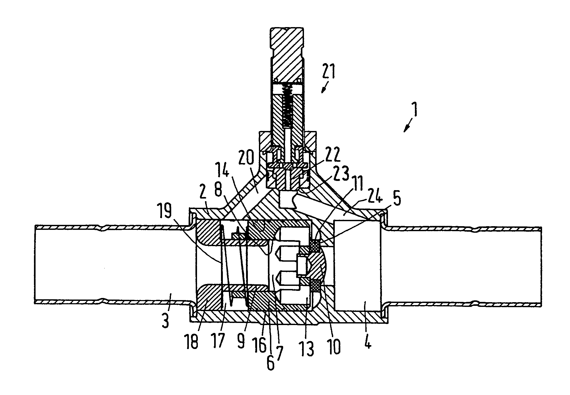
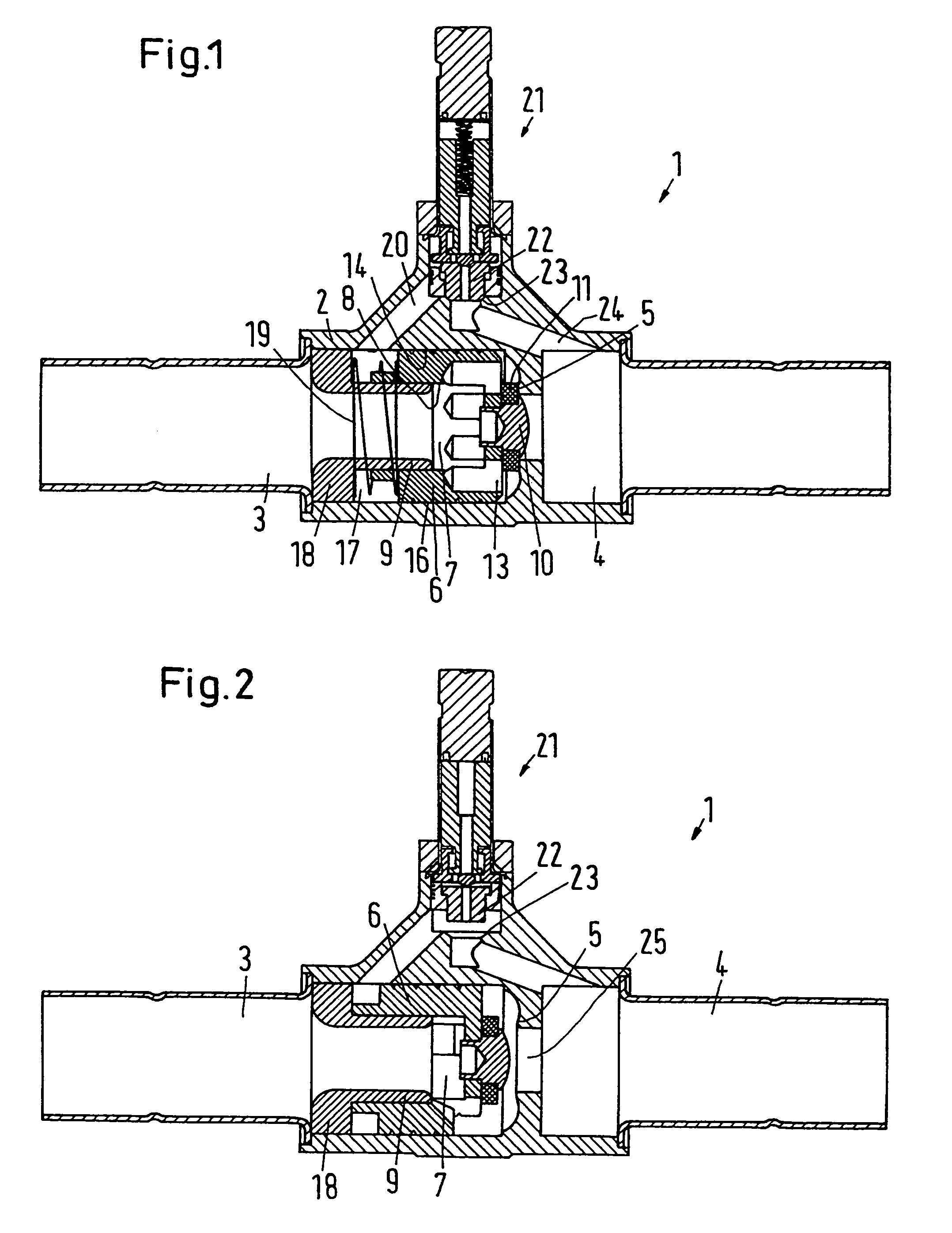
[0029]FIGS. 1 and 2 show an axial valve 1 with a housing 2 having an inlet 3 and an outlet 4. Between the inlet 3 and the outlet 4 is arranged a valve seat 5 which cooperates with a valve element 6.

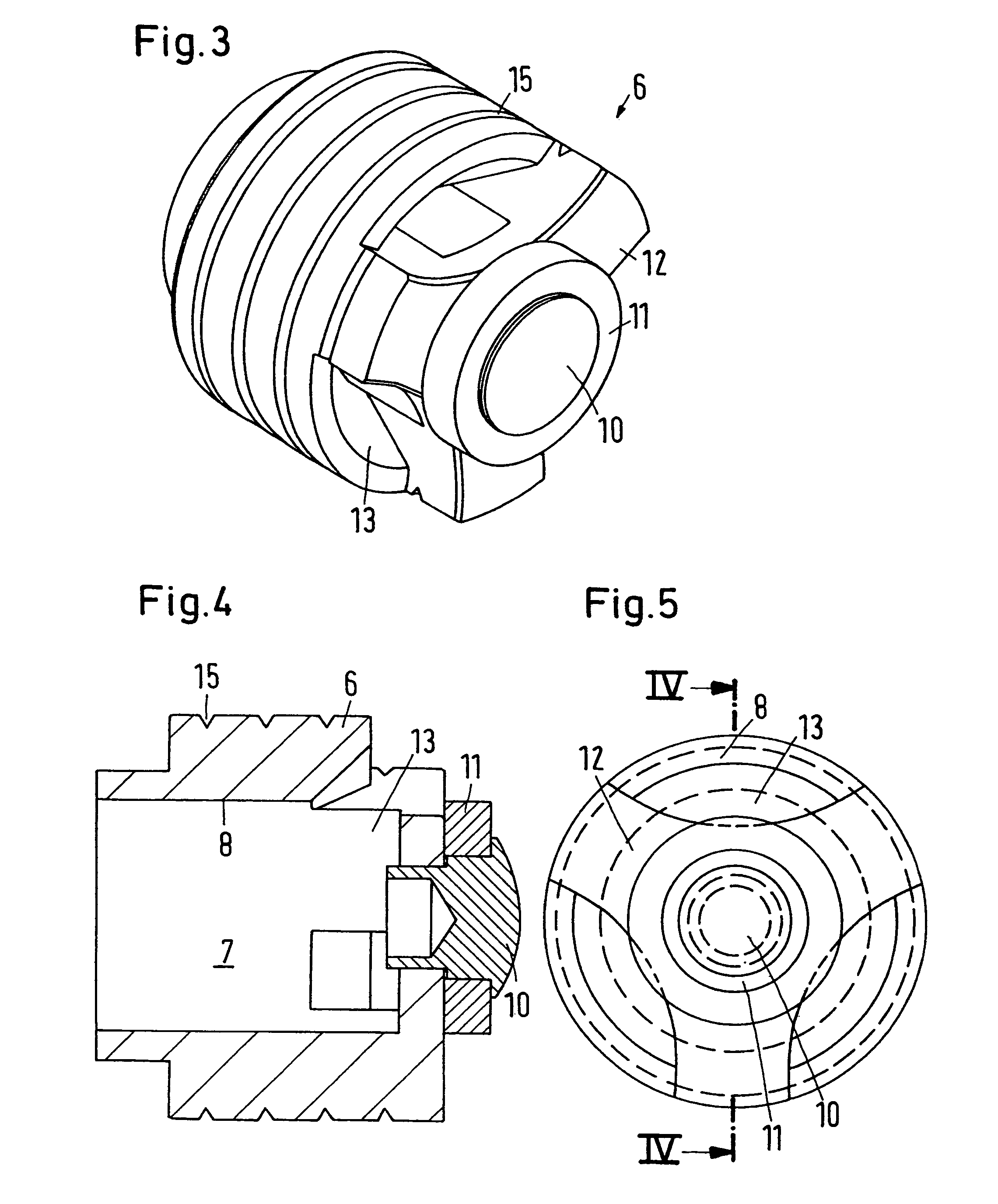
[0030]The valve element 6 has a hollow interior space 7. The interior space 7 has a wall 8 by means of which the valve element 6 is guided on the outside of a guide 9, which is arranged in and fixed relative to the housing 2. The valve element 6 is therefore telescopically supported on the guide. The guide 9 is formed as an insert fixed in the housing 2.

[0031]The valve element 6 has on its side which neighbors the outlet 4 a closed surface 10 surrounded by a seal 11 which ultimately comes to lie on the valve seat 5 when the valve element 6 is in the position illustrated in FIG. 1. The surface 10 stands in connection with the wall 8 through star shaped arms 12. Between the arms 12 are formed openings 13 through which fluid can flow which reaches the interior space 7 through the inlet 3, wh...


PUM


Abstract

An axial valve has a housing, an inlet, an outlet, a valve seat between the inlet and the outlet, and a valve element cooperating with the valve seat, and is controlled by a pilot valve arranged between the inlet and the outlet, with the valve element being moveable parallel to a flow path from the inlet to the outlet and surrounding an interior space. Without changing the external measurements of the valve an increased through flow is achieved in that a first section of the flow path leads through the interior space and a pressure space is arranged between the housing and the valve element, in which pressure space in the closed condition of the pilot valve a closing pressure is formed and applied to the valve element.

Description

CROSS-REFERENCE TO RELATED APPLICATIONS[0001]This application is entitled to the benefit of and incorporates by reference essential subject matter disclosed in German Patent Application No. 102 51 167.5 filed on Oct. 31, 2002.FIELD OF THE INVENTION[0002]The invention concerns an axial valve with a housing, an inlet, an outlet, a valve seat between the inlet and the outlet and a valve element cooperating with the valve seat, which is controlled by a pilot valve arranged between the inlet and the outlet, the valve element being moveable parallel to a flow path from the inlet to the outlet and surrounding an interior space.BACKGROUND OF THE INVENTION[0003]In one such axial valve, which is distributed by Danfoss A / S, Nordborg, Denmark, the valve element is guided in a cage arranged between the inlet and the outlet. The valve element is hollow. A spring is received in the hollow space which presses the valve element in the axial direction out of the cage and into engagement with the valv...

Claims


Application Information

Patent Timeline
IPC IPC(8): F16K31/40F16K31/36
CPCF16K31/406
Inventor LARSEN, SOEREN MICHAELJOERGENSEN, ERIK CASPERBIRKELUND, MICHAEL
Owner DANFOSS AS
Why Eureka
Try Eureka