Ink-jet printhead

a technology of inkjet printing and inkjet printing, which is applied in the direction of printing, etc., can solve the problems of many processes, difficult three-dimensional machining of the pressure chamber, the ink manifold and the nozzle in the same cavity plate, and the inability to form a damper chamber

Inactive Publication Date: 2005-10-18
BROTHER KOGYO KK
View PDF7 Cites 58 Cited by
  • Summary
  • Abstract
  • Description
  • Claims
  • Application Information

AI Technical Summary

Benefits of technology

[0008]The present invention addresses the foregoing problems and provides an ink-jet printhead that is rigid enough to stabilize the ink ejection characteristics of the nozzles and have a cavity unit that can effectively damp a pressure wave transmitted to the ink in a manifold chamber.

Problems solved by technology

In addition, three-dimensional machining of the pressure chamber, ink manifold, and nozzles in the same cavity plate is difficult and requires many processes.
However, this structure does not allow a damper chamber to be formed to face the ink manifold in the manifold plate.

Method used


Image

  • Ink-jet printhead
  • Ink-jet printhead
  • Ink-jet printhead

Examples


Embodiment Construction

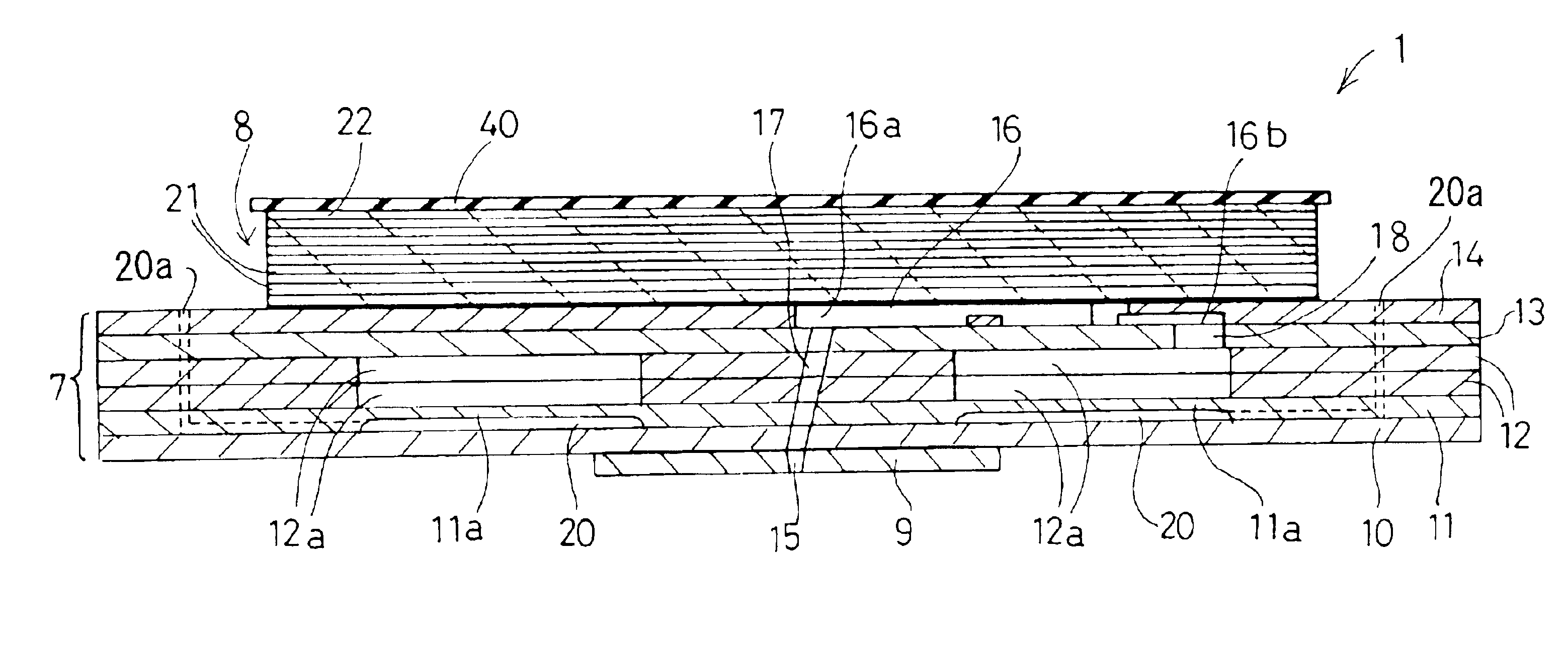
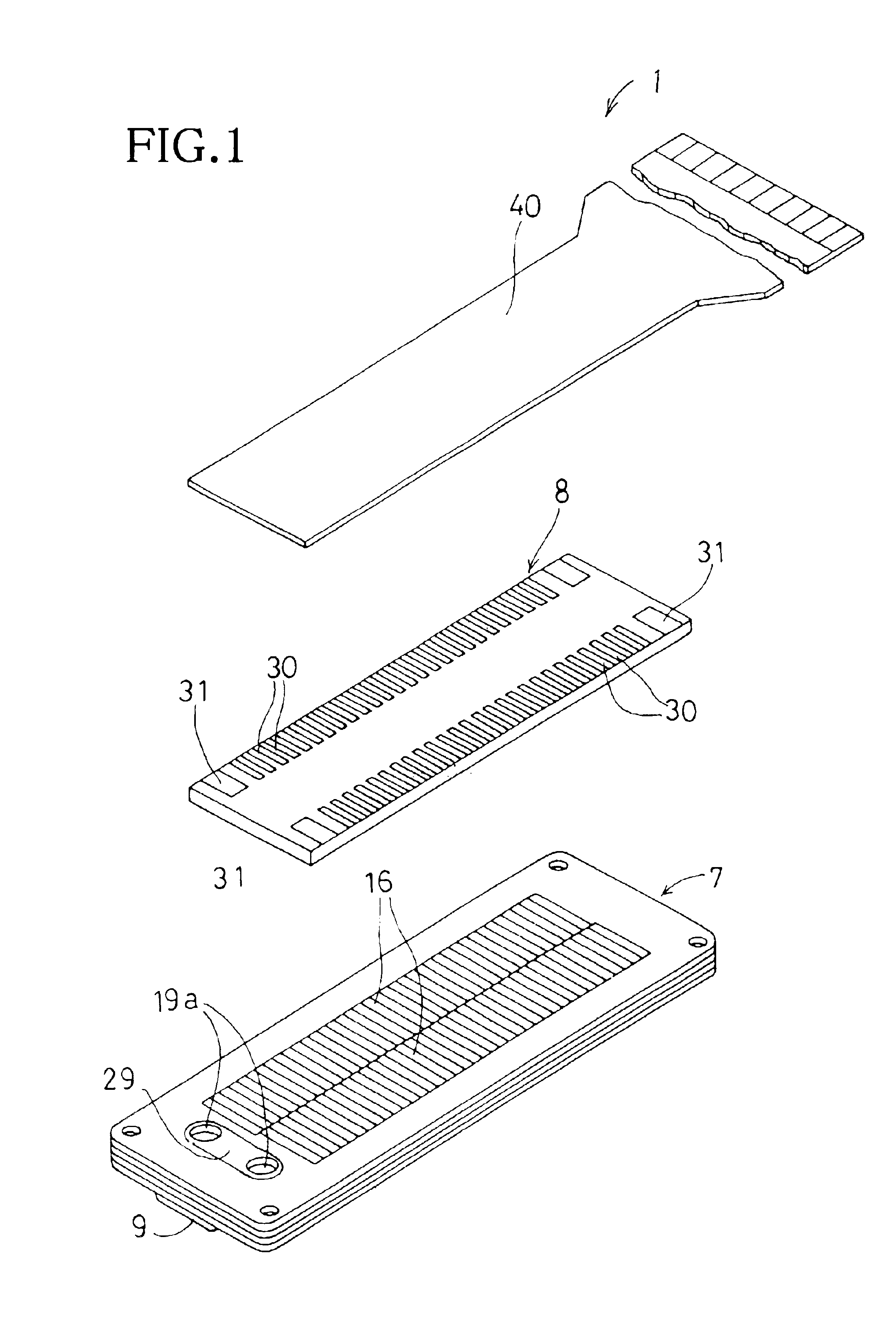
[0019]An ink-jet printhead 1 according to one embodiment of the invention will be described with reference to FIGS. 1 through 4. In the ink-jet printhead 1, a flexible flat cable 40 is bonded to an upper surface of a plate-shaped piezoelectric actuator 8 for connection with external devices, and the piezoelectric actuator 8 is bonded to a cavity unit 7. Ink is ejected from nozzles open at a lower surface of the cavity unit 7.

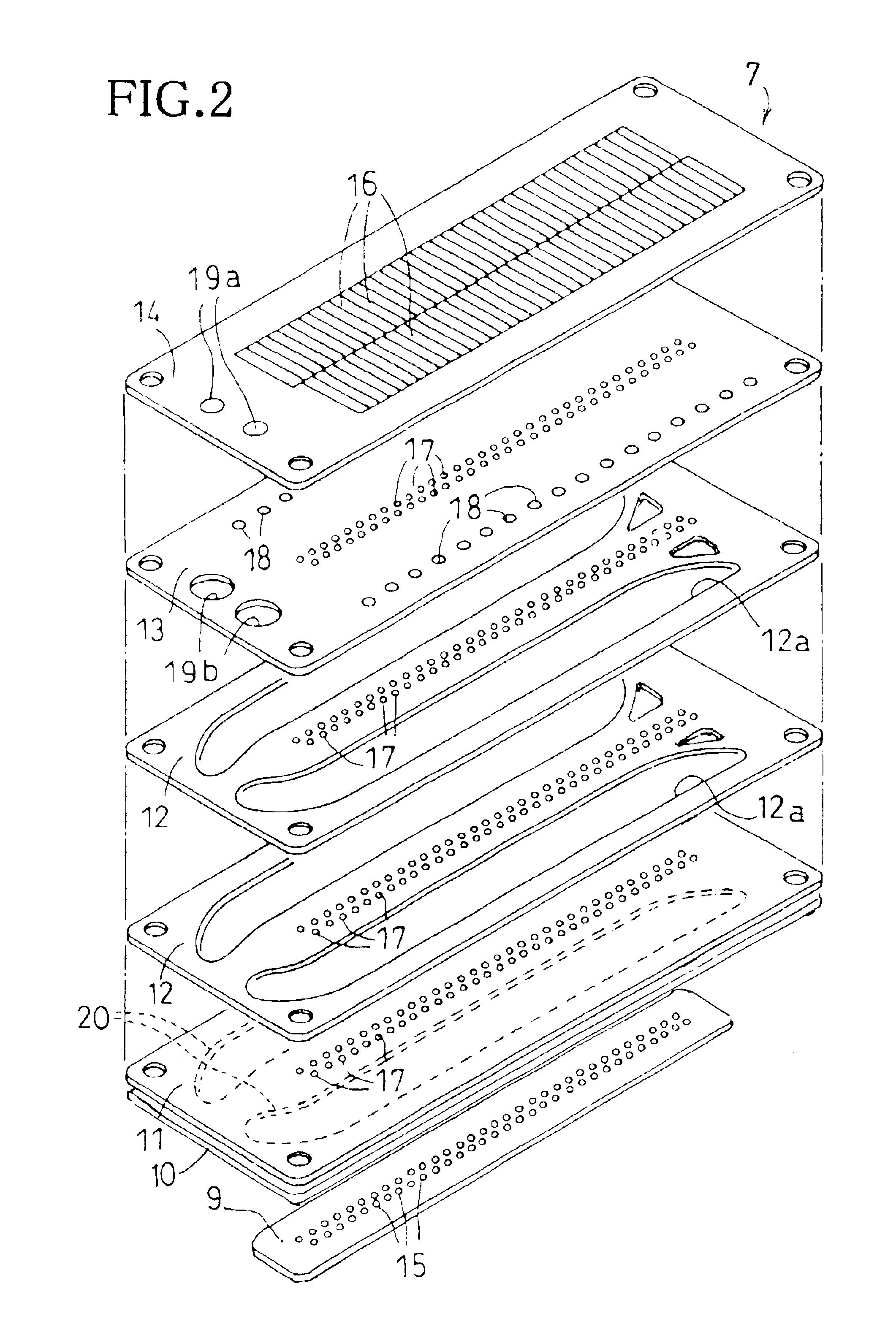
[0020]The structure of the cavity unit 7 will be described with reference to FIGS. 2 and 3. The cavity unit 7 is formed by laminating and bonding seven thin plates, that is, a nozzle plate 9, a cover plate 10, a damper plate 11, two manifold plates 12, 12, a spacer plate 13, and a base plate 14. In this embodiment, each plate 10, 11, 12, 12, 13, 14, except for the nozzle plate 9, is made of 42% nickel steel and has a thickness of about 50-150 μm. Openings and recesses are formed as ink passages and chambers, which will be described later, in these plates by elec...


PUM


Abstract

A cavity unit of an ink-jet printhead is formed by laminating a base plate formed with pressure chambers, a spacer plate, a manifold plate, a damper plate, a cover plate, and a nozzle plate formed with nozzles. The manifold plate is formed with a manifold chamber that penetrates through the manifold plate. The damper plate is formed with a recess on a side facing away from the manifold chamber and a damper wall left on a side facing the manifold chamber to have a partial thickness of the damper plate. The damper plate is bonded to the manifold plate on an opposite side from the base plate such that the damper wall is positioned to face the manifold chamber. The cover plate is bonded to the manifold plate to seal the recess. Because the damper plate is relatively thick while the damper wall is thin enough to absorb a pressure wave in the manifold chamber generated upon ink ejection, the damper plate is easy to handle.

Description

BACKGROUND OF THE INVENTION[0001]1. Field of Invention[0002]The invention relates to a piezoelectric ink-jet printhead that has a cavity unit including a plate with a damper wall.[0003]2. Description of Related Art[0004]As disclosed in U.S. Pat. No. 5,943,079, which is incorporated herein by reference, a prior art on-demand type ink-jet printhead includes a cavity plate, a piezoelectric plate, and a vibration plate (flexible film) placed as a diaphragm between the cavity plate and the piezoelectric plate. The cavity plate is formed with nozzles, pressure chambers communicating with the respective nozzles, and an ink manifold that communicates with the pressure chambers to supply ink thereto. The piezoelectric plate is provided with energy generating portions, such as piezoelectric elements, that are selectively driven to pressurize the ink in the pressure chambers for ejection though the nozzles.[0005]When any energy generating portion is driven, the corresponding pressure chamber i...

Claims


Application Information

Patent Timeline
Patent Type & Authority Patents(United States)
IPC IPC(8): B41J2/055B41J2/14B41J2/045B41J2/16
CPCB41J2/055B41J2/14209B41J2002/14217B41J2002/14225B41J2002/14306B41J2002/14419
Inventor ITO, ATSUSHI
Owner BROTHER KOGYO KK
Why Eureka
Try Eureka