Thin plate stacked structure and ink-jet recording head provided with the same

a technology stacked structure, which is applied in printing and other directions, can solve the problems of ink leakage and other problems, and achieve the effect of ensuring the performance of ink-jet printer head, stable adhesive/seal layer, and avoiding liquid leakag

Inactive Publication Date: 2005-10-18
BROTHER KOGYO KK
View PDF16 Cites 9 Cited by
  • Summary
  • Abstract
  • Description
  • Claims
  • Application Information

AI Technical Summary

Benefits of technology

[0018]In the stack according to the present invention, the air release hole is formed to be larger than the width of the release groove, and the air release hole is formed to be larger than the opening disposed on the outermost layer. Accordingly, the cavity volume (capacity) of the air release hole is increased. Therefore, any excessive adhesive is accumulated in the air release hole, and it is possible to greatly decrease the amount of the adhesive outflowing to the outside of the cavity unit. Therefore, it is possible to suppress the adhesion of the adhesive to the pressing and joining apparatus, which would be otherwise caused by the outflow to the outside from the air release hole of the thin plate-shaped part disposed at the outermost layer. It is possible to avoid any extra cleaning operation which would be otherwise performed to clean and treat the outflow adhesive. Further, it is also possible to decrease the frequency of exchange of the installation of the sheet to the pressing and joining apparatus in order to avoid any adhesion of the adhesive thereto when the operation for pressing and joining the thin plates is performed.
[0034]In the thin plate stacked structure according to the fourth aspect, the anchor holes of one plate are not connected to one another in the in-plane direction of the plate. Accordingly, the rigidity against the bending moment is not greatly decreased (lowered) locally. It is possible to obtain the stacked and adhered structure of the thin plate-shaped parts having the high degree of strength even though the thickness is thin. Further, a part of the adhesive disposed between the stacked plates enters the anchor holes, and the adhesive is adhered to at least portions of the circumferential surfaces of the anchor holes so that the force is allowed to act to fasten the both plate (referred to as “anchoring effect”). Therefore, it is possible to effect the powerful joining function as compared with the joining force brought about by the adhesive based on only the areas of the stacking surfaces at which the plates are opposed to one another.

Problems solved by technology

When the actuator is repeatedly operated, the following first problem has arisen due to the fatigue phenomenon caused by the stress concentration brought about by the stress exerted repeatedly on the portion of the groove parallel to the short side.
That is, any crack appears in the plate 201 during the use for a long period of time, the adhesive surface between the respective plates is exfoliated, and any leakage of the ink is apt to occur.
However, the following second problem has arisen.
The first and second problems may also arise during the assembling of an electronic part constructed by staking a thin plate formed with a minute pattern onto another thin plate.

Method used


Image

  • Thin plate stacked structure and ink-jet recording head provided with the same
  • Thin plate stacked structure and ink-jet recording head provided with the same
  • Thin plate stacked structure and ink-jet recording head provided with the same

Examples


first embodiment

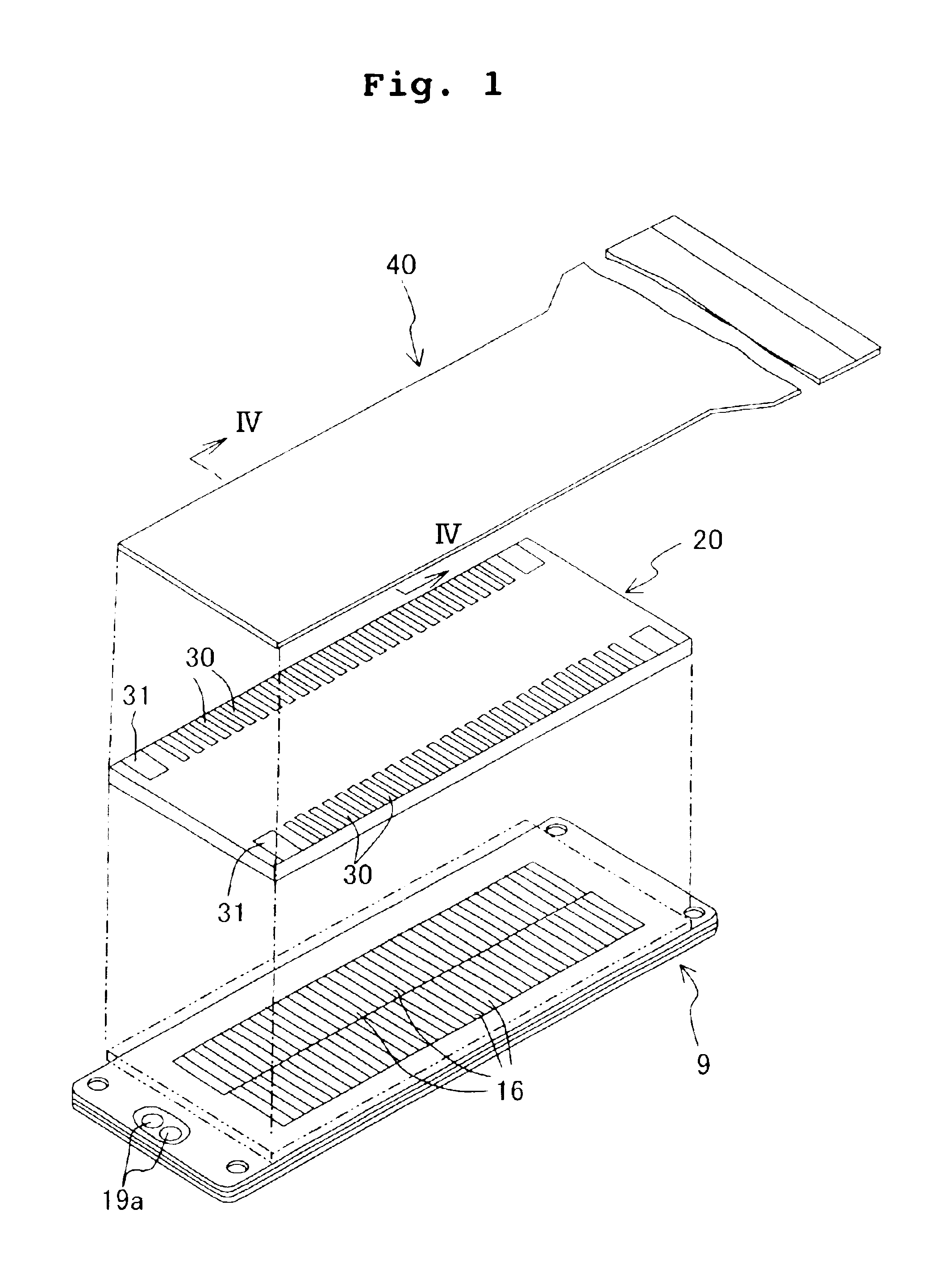
[0056]An embodiment of the present invention will be explained below with reference to the drawings. FIGS. 1 to 7 show a piezoelectric ink-jet printer head according to a first embodiment of the present invention. In FIG. 1, a flexible flat cable 40 is overlapped and joined with an adhesive to effect the connection to an external apparatus on an upper surface of a plate type piezoelectric actuator 20 which is joined to a cavity unit 9 made of metal plates. The ink is jetted downwardly from nozzles 15 which are open on the lower surface side of the lowermost layer of the cavity unit 9.

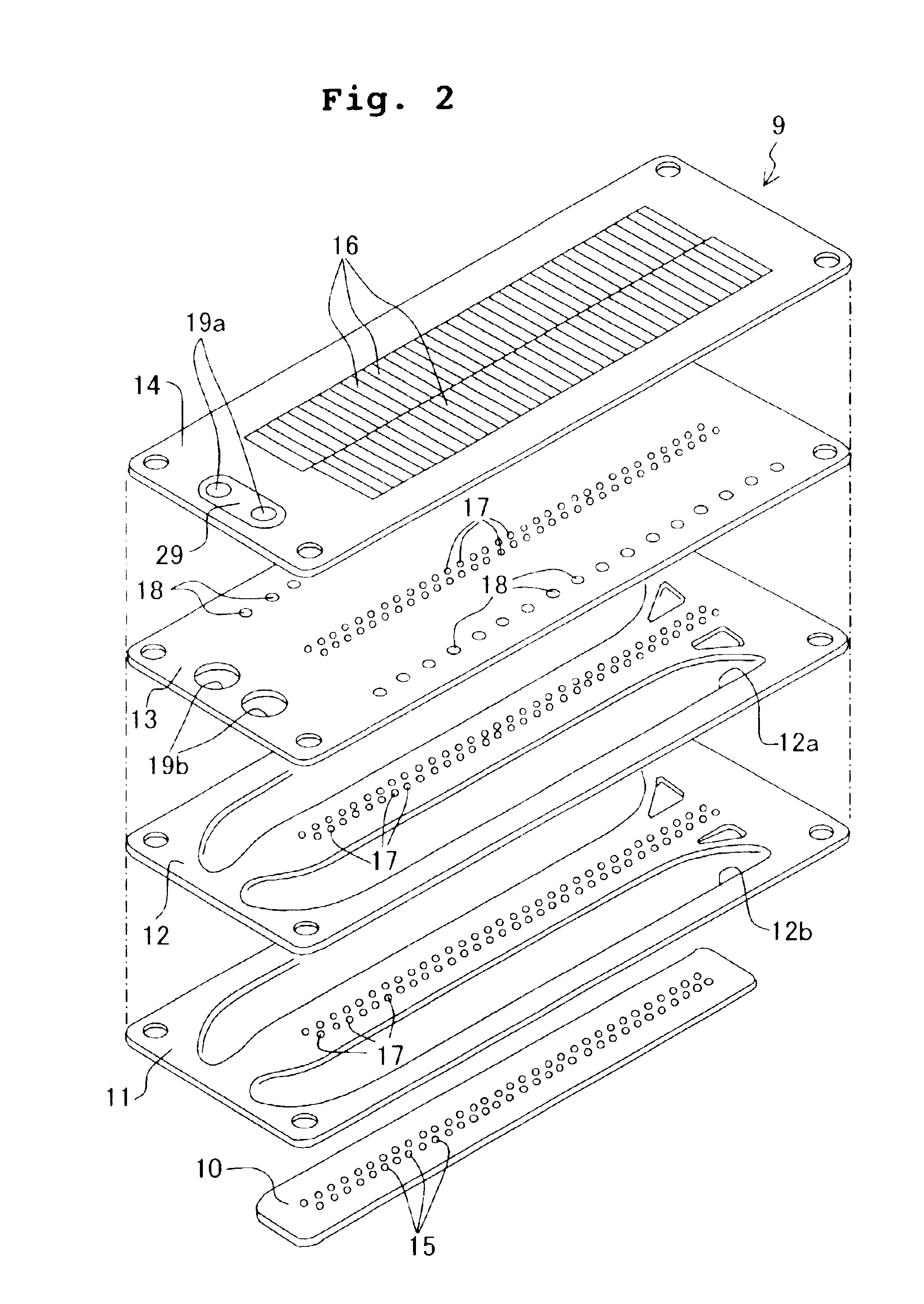
[0057]The cavity unit 9 is constructed as shown in FIGS. 2 to 6. That is, the cavity unit 9 has such a structure that five thin plates, i.e., a nozzle plate 10, two manifold plates 11, 12, a spacer plate 13, and a base plate 14 are overlapped, joined, and stacked with an adhesive respectively. In this embodiment, each of the plates 11, 12, 13, 14 is made of a 42% nickel alloy steel plate having a thickn...

second embodiment

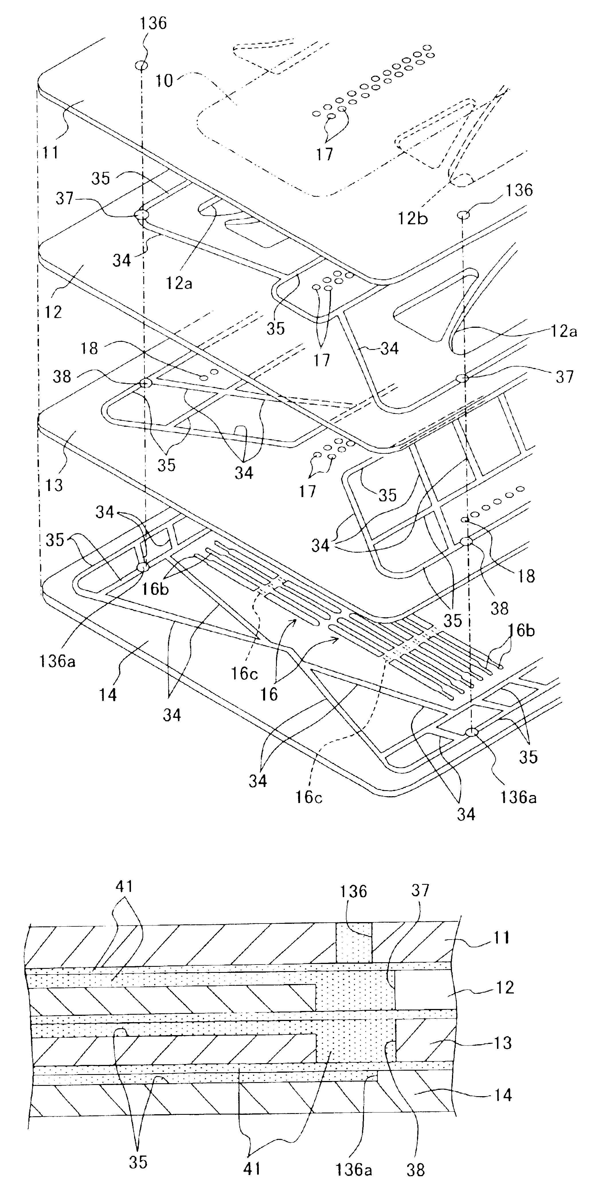
[0074]A second embodiment of the piezoelectric ink-jet printer head according to the present invention will be explained below. The head and a method for producing the same are approximately the same as those described in the first embodiment except that the air release hole and the release groove of the cavity unit differ in structure as explained below. In the cavity unit, as shown in FIGS. 9, 10A, and 10B, thin width release grooves 34, 35 for the adhesive are formed as recesses on first surfaces of the mutually opposing surfaces of the plates which are disposed adjacently in the vertical direction. In FIG. 9, the release grooves 34, 35 for the adhesive, which are formed on the first surfaces of the base plate 14 disposed at the lowermost layer, the spacer plate 13 disposed at the second layer from the bottom, and the manifold plate 12 disposed at the third layer from the bottom, are arranged so that they are directed upwardly.

[0075]Air release holes 37, 38 are bored at positions...

third embodiment

[0089]A third embodiment of the present invention will be explained below with reference to FIG. 13. FIG. 13 shows shapes of release grooves 142 as viewed in plan view according to a third embodiment. In this embodiment, the respective release grooves 142 are formed by means of the half etching to have a meandering form as viewed in plan view on one surface of each of plates 11 to 14. FIG. 13 shows a case in which the plurality of meandering release grooves 142 are formed to have long dimensions along the long side on one surface of the spacer plate 13. Air release holes 43, which penetrate in the plate thickness direction of the spacer plate 13, are provided at appropriate positions of the release grooves 142. The other constitutive components of the spacer plate 13 are the same as those in the first embodiment. Therefore, the same constitutive components are designated by the same reference numerals, any detailed explanation of which is omitted.

[0090]Few portions of the release gr...


PUM


Abstract

A thin plate stacked structure is formed of a plurality of thin plates, which include at least one liquid flow passage thin plate provided with a liquid flow passage having a predetermined pattern formed on at least one surface, are stacked with an adhesive. The stacked structure further includes a release groove, an air release hole and an opening that is formed on the thin plate disposed at an outermost layer of the thin plate stack. The air release hole has a diameter which is larger than the width of the release groove and which is larger than the opening disposed on the outermost layer. Any excessive adhesive is accumulated in the air release hole, and it is possible to greatly decrease the amount of the adhesive outflowing to the outside of a cavity unit.

Description

BACKGROUND OF THE INVENTION[0001]1. Field of the Invention[0002]The present invention relates to a structure obtained by adhering and fixing, in a stacked form, a plurality of thin plate-shaped parts to be used, for example, for an ink-jet printer head and an electronic part.[0003]2. Description of the Related Art[0004]Examples of the ink-jet printer head of the on-demand type are described, for example, in Japanese Patent Application Laid-open No. 62-111758 corresponding to U.S. Pat. Nos. 4,680,595 and 4,730,197, Japanese Patent Application Laid-open No. 10-119263, and Japanese Patent Application Laid-open No. 2002-96478 corresponding to U.S. patent application Publication No. US2002 / 0036678 A1. As described in these patent documents, a structure is disclosed, in which a jetting pressure-generating member such as a driving piezoelectric element is secured, corresponding to each of portions of a plurality of pressure chambers, to a back surface of a cavity unit composed of a plurali...

Claims


Application Information

Patent Timeline
Patent Type & Authority Patents(United States)
IPC IPC(8): B41J2/14B41J2/16
CPCB41J2/14209B41J2/1609B41J2/1623B41J2002/14217B41J2002/14225B41J2002/14362B41J2002/14306
Inventor ITO, ATSUSHI
Owner BROTHER KOGYO KK
Why Eureka
Try Eureka