Filter frame

Inactive Publication Date: 2005-10-18
3M INNOVATIVE PROPERTIES CO
View PDF70 Cites 40 Cited by
  • Summary
  • Abstract
  • Description
  • Claims
  • Application Information

AI Technical Summary

Benefits of technology

[0017]In another aspect of the invention, the perimeter structure contains indentations or narrow regions that allow the frame to be readily manually gra

Problems solved by technology

After a period of use, these filters become dirty or clogged and must be replaced.
Because the frame and screen are discarded with the assembly even though it is only the filter material that is no longer functional, there is unnecessary waste and cost associated with such fil

Method used


Image

  • Filter frame
  • Filter frame
  • Filter frame

Examples


Embodiment Construction

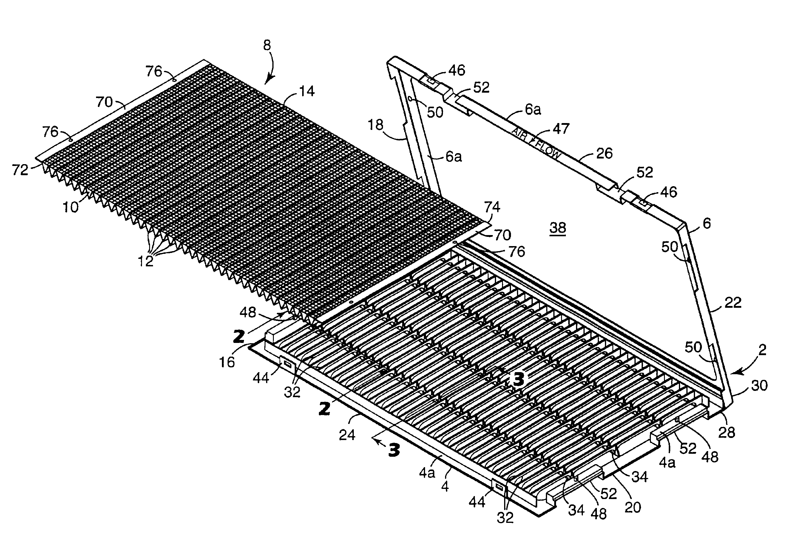
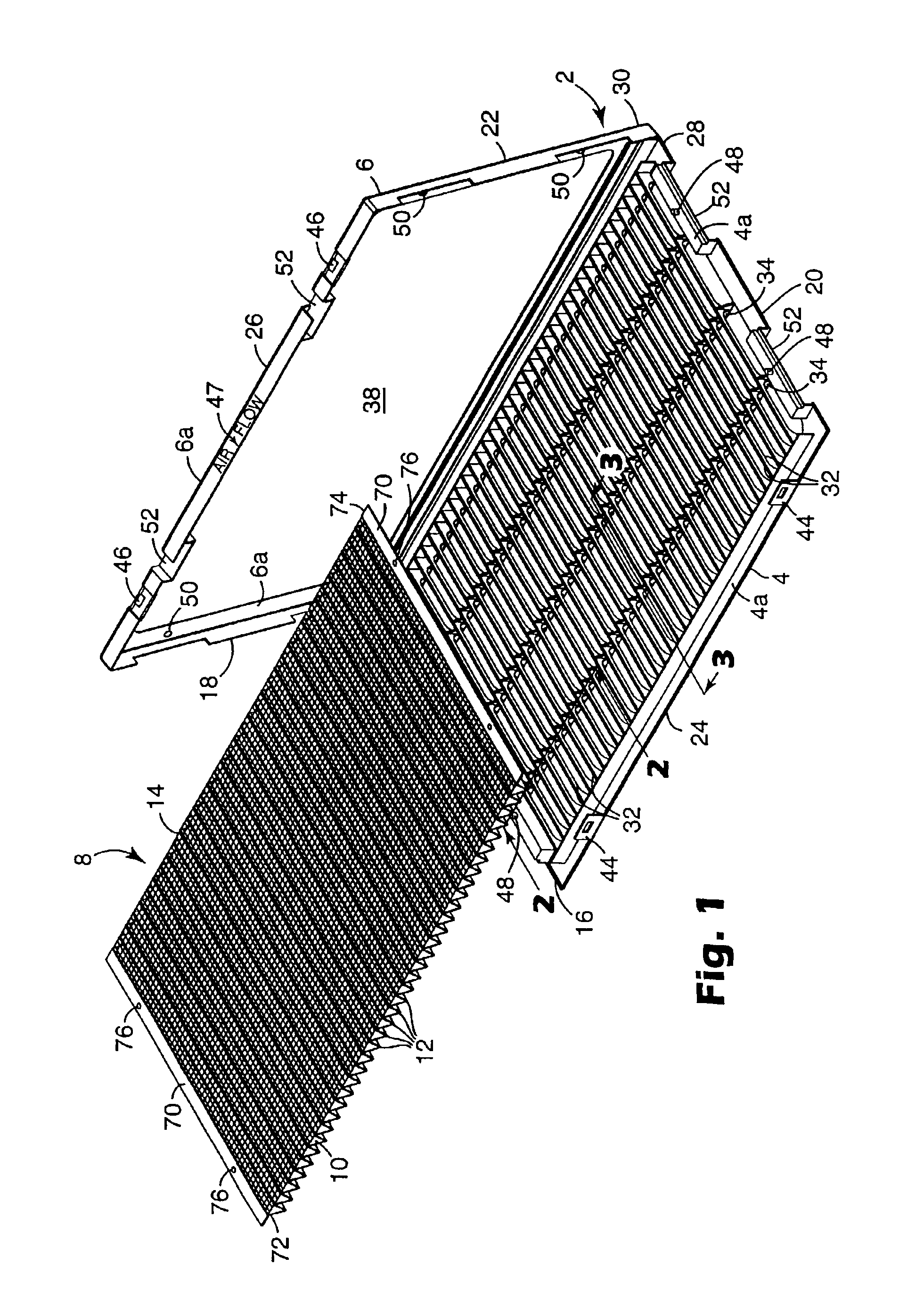
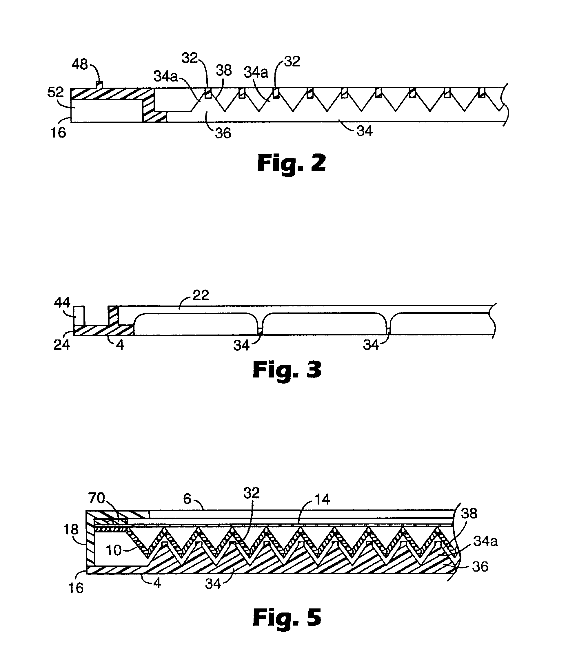
[0028]Referring now to the drawings, wherein like reference numerals refer to like or corresponding parts throughout the several views, FIGS. 1-5 show a reusable filter frame 2 including a base 4 and an optional cover 6 for use with a removable pleated filter element 8 having an appropriate size and configuration to fit into the base 4. Alternatively, the filter element 8 may be arranged in the cover 6 which is then closed over the base 4. The filter frame 2 has a generally planar rectangular configuration and intended for use in an air duct of a residential air handling system, such as a furnace.

[0029]The filter element 8 generally includes filter media 10 having a plurality of pleats 12 and a spacing structure 14 attached to successive pleat tips. The filter element 8 is described more fully below with reference to FIGS. 6-8.

[0030]The base 4 and cover 6 include perimeter structures 4a, 6a, respectively, having corresponding first ends 16, 18 and second ends 20, 22, respectively, a...


PUM

PropertyMeasurementUnit
Structureaaaaaaaaaa
Perimeteraaaaaaaaaa

Abstract

A reusable filter frame adapted to receive a replaceable filter element includes a base and a cover connected with the base. The base includes a plurality of longitudinal rails and a plurality of transverse ribs for supporting and spacing the filter element. The filter frame also includes a securing mechanism for securing the filter element to the frame and maintaining the filter element in its expanded condition.

Description

FIELD OF THE INVENTION[0001]The present invention relates generally to filters and, more particularly, to an air filter including a reusable frame and a collapsible, replaceable, pleated filter element.BACKGROUND OF THE INVENTION[0002]Many conventional residential heating and cooling systems include a disposable filter. These filters typically include a frame, a filter material formed of glass fibers or similar material, and a mesh screen or the like that supports the filter material. After a period of use, these filters become dirty or clogged and must be replaced. This is accomplished by replacing the entire filter assembly with a new filter and discarding the old one. Depending on the use of the filter, replacement may be required several times a year. Because the frame and screen are discarded with the assembly even though it is only the filter material that is no longer functional, there is unnecessary waste and cost associated with such filters. In addition, because these filt...

Claims


Application Information

Patent Timeline
IPC IPC(8): B01D46/52B01D46/00
CPCB01D46/0005B01D46/008B01D46/523B01D46/10Y10S55/31B01D46/88
Inventor KUBOKAWA, JAMES O.ROGOWSKI, BEN G.TEDHAM, THOMAS A.
Owner 3M INNOVATIVE PROPERTIES CO
Why Eureka
Try Eureka