
Motor driving control device

a technology for controlling devices and motors, applied in the direction of motor/generator/converter stoppers, dynamo-electric gear control, dynamo-electric converter control, etc., can solve the problem of inevitability of system costs, and achieve the effect of reducing the number of current sensors

Inactive Publication Date: 2005-10-18
TOYOTA CENT RES & DEV LAB INC +1
View PDF10 Cites 13 Cited by
  • Summary
  • Abstract
  • Description
  • Claims
  • Application Information

AI Technical Summary

Benefits of technology

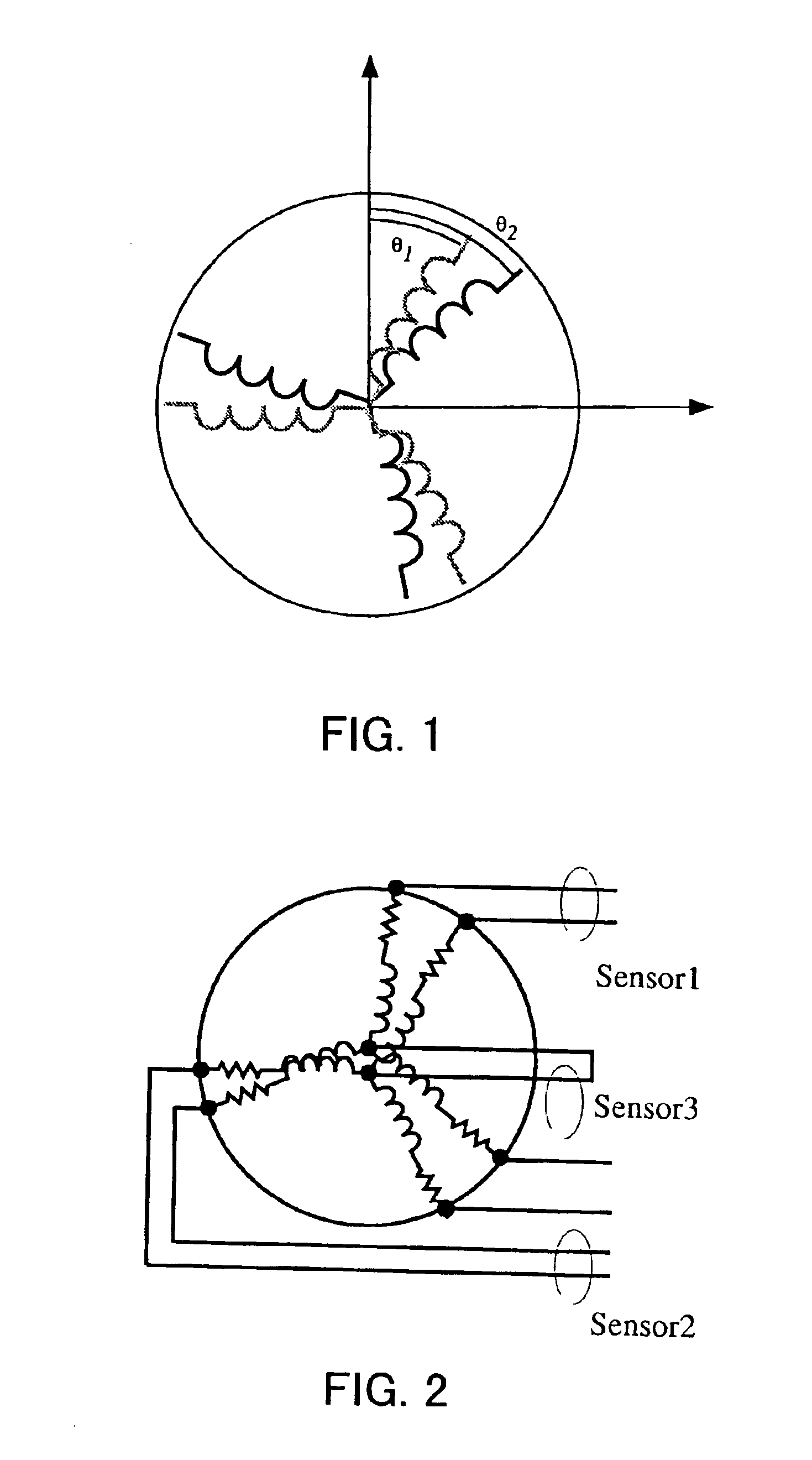
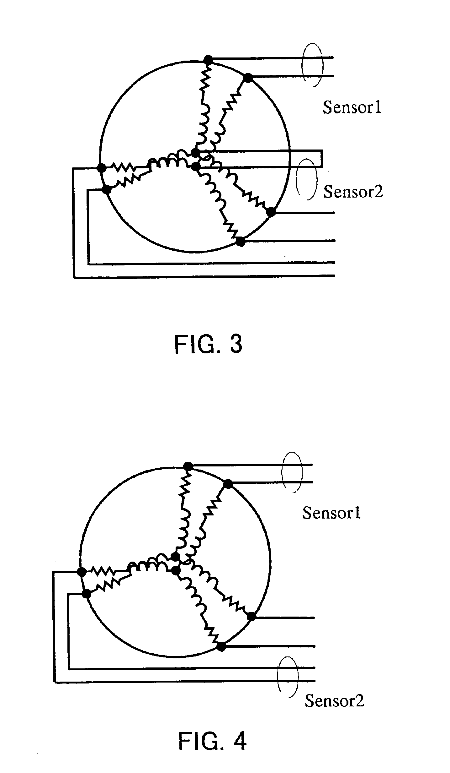
The present invention reduces the number of current sensors required for motor control. It uses a model to estimate the motor current based on the measurements of a reduced number of coil currents. This results in a more efficient and cost-effective motor control system. Additionally, the invention allows for the measurement of additional phase currents, which further improves the accuracy of the motor control.

Problems solved by technology

As such a large number of current sensors are required, a resultant system is inevitably expensive.

Method used


Image

  • Motor driving control device
  • Motor driving control device
  • Motor driving control device

Examples


Embodiment Construction

[0023]A preferred embodiment of the present invention will be described with reference to the accompanied drawings.

[0024]In this embodiment, an observer of a six-phase motor is defined so that coil currents of the six-phase motor are calculated using the defined observer and a fewer number of sensors to control driving of the six-phase motor.

[Basic Structure]

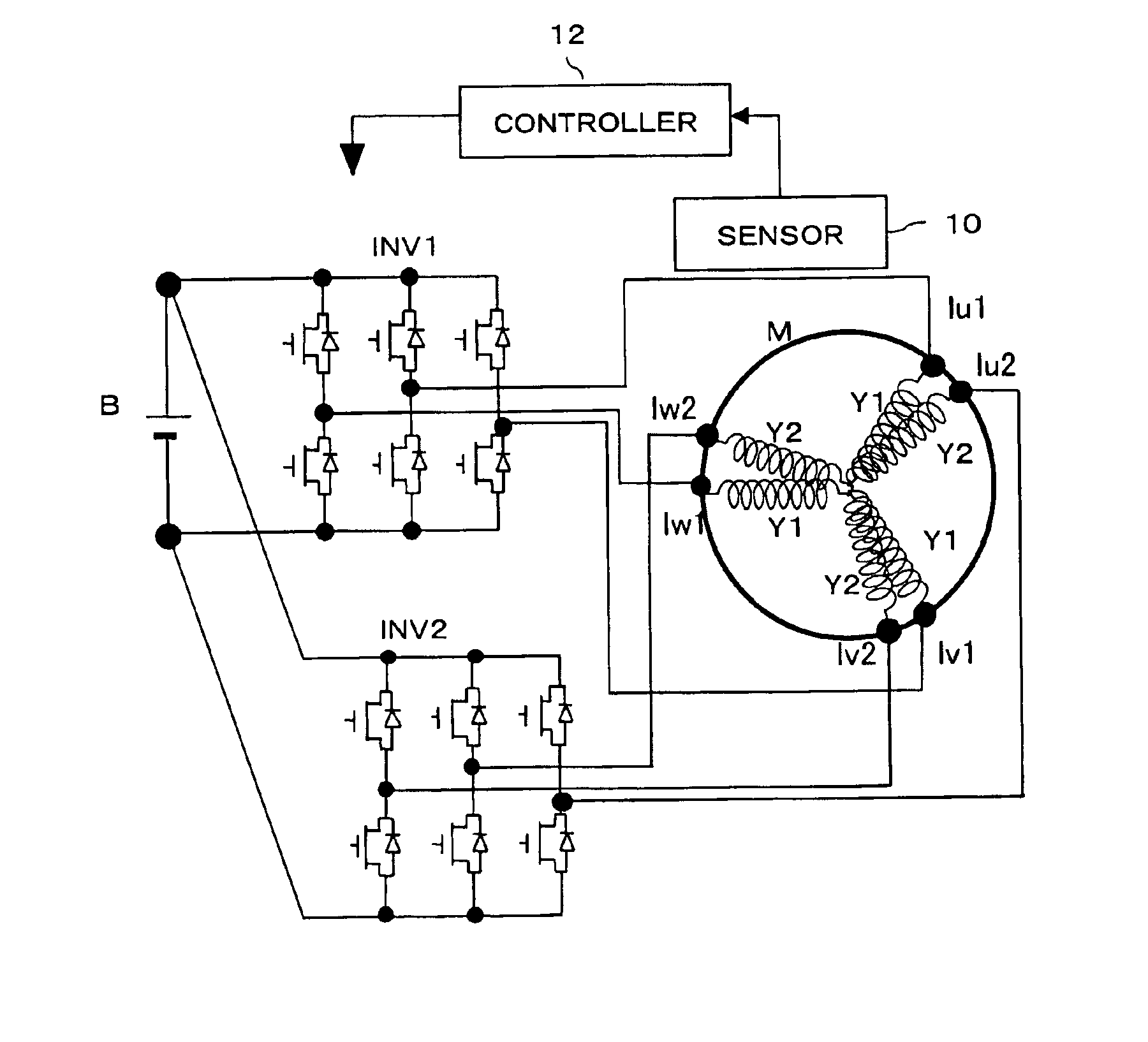
[0025]FIG. 11 shows a basic structure of a six-phase motor M, which comprises two three-phase coils Y1 and Y2. The three-phase coil Y1 is connected to an inverter INV1, while the three-phase coil Y2 is connected to an inverter INV2. The inverters INV1 and INV2 each has three arms each comprising a pair of serially,connected switching elements, and connection points between the respective paring transistors (switching elements) are connected to the respective three coil ends of the corresponding three-phase coil Y1 or Y2.

[0026]Inputs of the inverters INV1 and INV2 are connected to a battery B. A sensor 10 is provided for multiple...


PUM


Abstract

Two inverters (INV1, INV2) supply phase currents to three-phase coils (Y1, Y2). Although two phase currents must conventionally be measured and four current sensors are thus required, according to the present invention, the number of phase currents to be measured is reduced as a result of use of an observer for phase current estimation.

Description

BACKGROUND OF THE INVENTION[0001]1. Field of the Invention[0002]The present invention relates to a driving control device for a motor having a plurality of multi-phase coils for generating a rotating magnetic field to cause a rotor to rotate.[0003]2. Description of the Related Art[0004]Conventional AC motors, such as permanent magnetic motors and induction motors, use a stator coil to form a rotating magnetic field to thereby cause the rotor to rotate. Such AC motors use an inverter to control a stator coil current, and thereby can advantageously achieve control of an output torque over a wide range, as well as collection of a regenerative power in a battery.[0005]The most common example of such an AC motor may be a three-phase motor having a three-phase coil with three phases displaced by 120 degrees from one another. Some systems, such as a system for driving two or more three-phase motors, may have two or more three-phase coils, and some motors having two or more three-phase coil...

Claims


Application Information

Patent Timeline
Patent Type & Authority Patents(United States)
IPC IPC(8): H02P21/00H02P25/16H02P25/22H02P29/00H02P25/08
CPCH02P21/0035H02P25/22H02P21/22
Inventor NAKAI, HIDEOFUMA, HIROOINAGUMA, YUKIONAKAMURA, SEIJI
Owner TOYOTA CENT RES & DEV LAB INC
Learn More