Transmitter for operating rolling code receivers

a technology for transmitting devices and receivers, applied in the field of security systems, can solve problems such as out of synchronization between transmitters and receivers

Inactive Publication Date: 2005-10-18
TSUI PHILIP Y W
View PDF20 Cites 42 Cited by
  • Summary
  • Abstract
  • Description
  • Claims
  • Application Information

AI Technical Summary

Problems solved by technology

However, where the transmitter transmits a code, but the receiver does not receive the transmitted code, the transmitter and receiver will be out of synchronization.

Method used


Image

  • Transmitter for operating rolling code receivers
  • Transmitter for operating rolling code receivers
  • Transmitter for operating rolling code receivers

Examples


Embodiment Construction

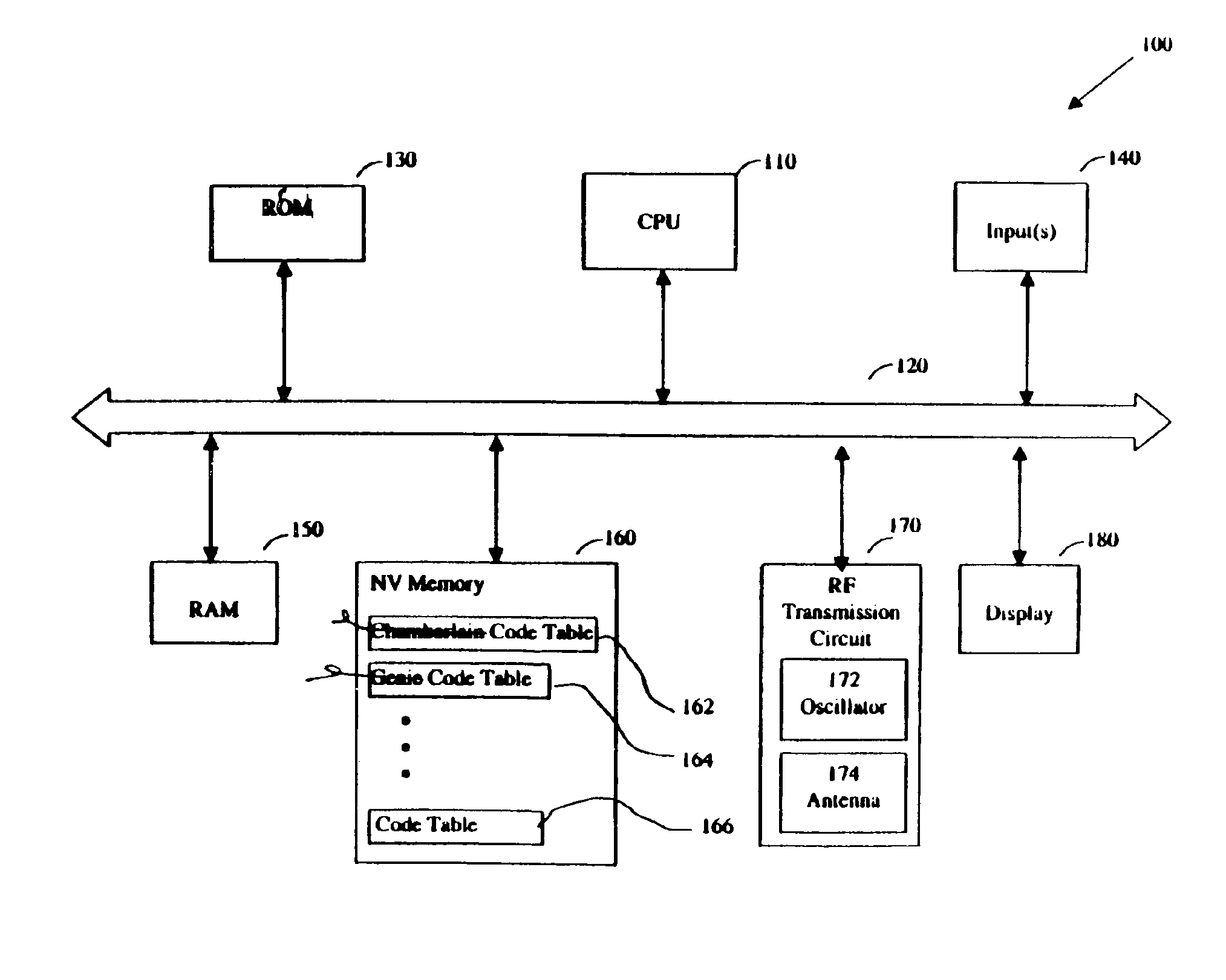
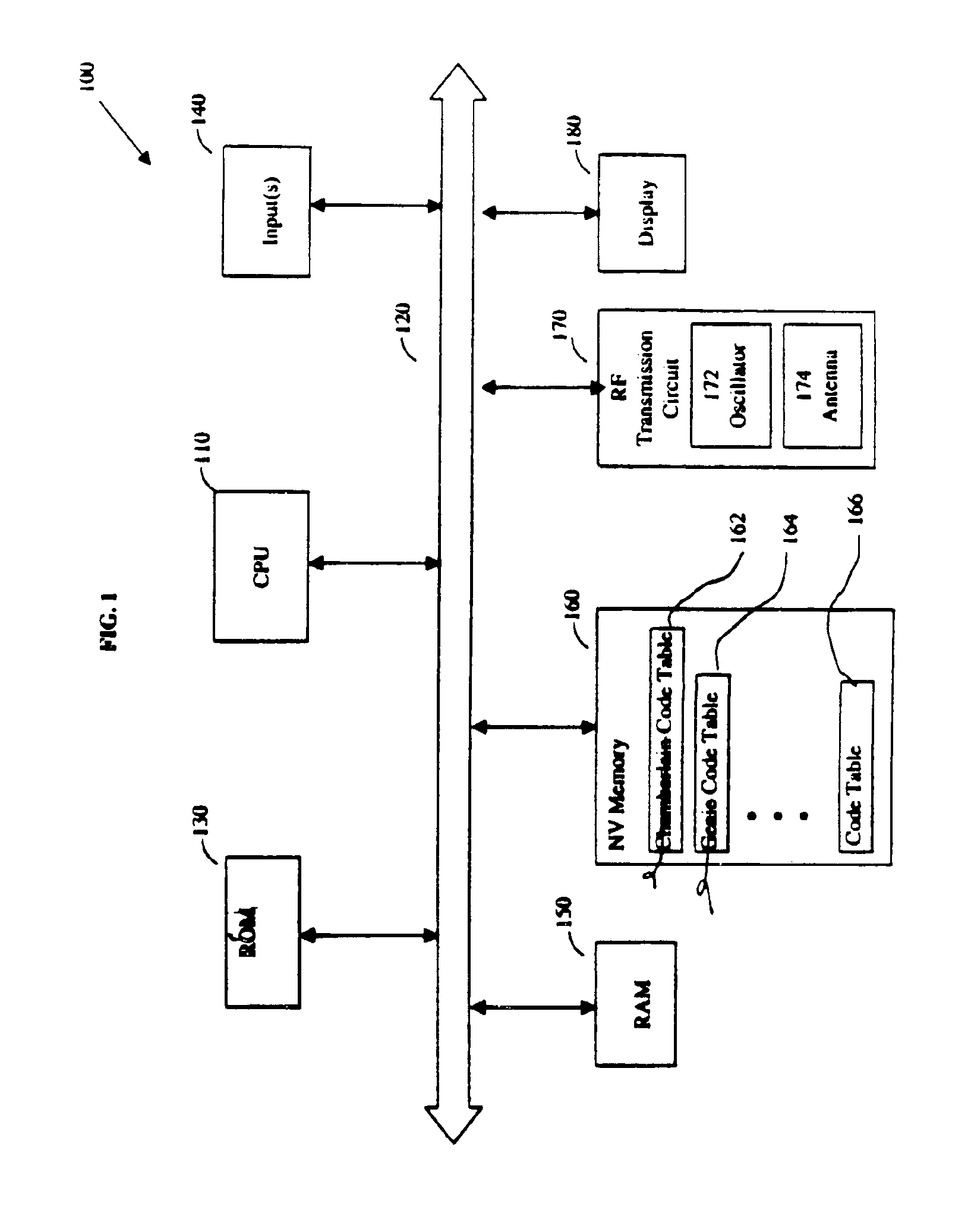
[0016]One aspect of the present disclosure relates to providing a fixed code transmitter that can be used to operate a rolling code receiver to actuate a controlled device such as a garage door, car alarm, etc. In one embodiment, a plurality of identified codes emitted from a rolling code transmitter are captured and stored in a transmitter. Each time the transmitter is actuated, one or more of the stored fixed codes are transmitted to a rolling code receiver, which will accept and be activated by at least one code. The transmitter may also be used to operate a plurality of different rolling code receivers. The transmitter may include one or more inputs which allow(s) a user to select which of one or more rolling code receiver types to control. The transmitter may then control the selected rolling code receiver by retrieving the one or more fixed codes corresponding to the selected rolling code receiver from memory and transmitting the one or more fixed codes to the selected receive...


PUM


Abstract

A fixed transmitter for operating a rolling code receiver is disclosed. A set of fixed codes is captured from a rolling code transmitter that is used to actuate a corresponding rolling code receiver. The set of fixed codes is stored in a memory of a fixed code transmitter. The fixed code transmitter, upon each actuation, transmits one or more codes of the set of fixed codes to operate the rolling code receiver. The set of stored fixed codes in the fixed code transmitter has fewer codes than a total number of unique codes that can be generated by the rolling code receiver.

Description

BACKGROUND[0001]1. Field of the Invention[0002]The present disclosure is directed in general to security systems and in particular to a security system that includes a transmitter for operating a rolling code receiver.[0003]2. Description of the Related Art[0004]Transmitter-receiver controller systems are widely used for remote control and / or actuation of devices or appliances such as garage door openers, gate openers, and security systems. Rather than transmitting a single code N to operate the receiver, rolling code technology is based on the idea that the recognized operating code of the security system changes each time an operating code is provided. The activation code is altered each time in both the transmitter and the receiver according to a rolling code algorithm, which produces a specific number of possible code combinations. In most cases, the transmitter and receiver of a rolling code system both contain a synchronized code generator that calculates a new operating code ...

Claims


Application Information

Patent Timeline
Patent Type & Authority Patents(United States)
IPC IPC(8): G08C19/16G08C19/28
CPCG08C19/28
Inventor TSUI, PHILIP Y.W.
Owner TSUI PHILIP Y W
Why Eureka
Try Eureka