Self-adjusting alarm system

a self-adjusting, alarm system technology, applied in the direction of anti-theft devices, instruments, mechanical vibrations of burglar alarms, etc., can solve the problems of triggering a false alarm on a vehicular, home, or business security system, non-intrusive and harmless contact or vibrations to a vehicle, etc., to improve the security of vehicles, homes, and reduce the number of false alarm annunciations.

Inactive Publication Date: 2005-10-18
JBS TECH +1
View PDF9 Cites 25 Cited by
  • Summary
  • Abstract
  • Description
  • Claims
  • Application Information

AI Technical Summary

Benefits of technology

[0009]It is an object of the applicant's invention to improve the security of vehicles, homes, and businesses. It is also an object of the applicant's invention to reduce the nu

Problems solved by technology

One problem with these previously known systems is the susceptibility to false alarms.
Vehicles are often parked in areas such as parking garages, shopping mall parking lots, or near heavily traveled roads, or railroad tracks, where they are susceptible to non-hostile vibrations and/or incidental or nonintrusive bumping or contact.
In addition, various weather conditions can also cause nonintrusive and harmless contact or vibrations to a vehicle.
For example, thunder, hail, or even heavy rain can, at times, trigger a false alarm on a vehicular, home, or business security system.
Similarly, motion detectors used in vehicles, homes, or businesses are susceptible to false alarms.
Similarly, in a home or business context, pets, internal air handling systems blowing papers, or external wind blowing branches next to windows can also trigger false alarms.
In addition, in the context of vehicular radar detectors, various radiated energy can create a false indication of the presence of law enforcement

Method used


Image

  • Self-adjusting alarm system
  • Self-adjusting alarm system
  • Self-adjusting alarm system

Examples


Embodiment Construction

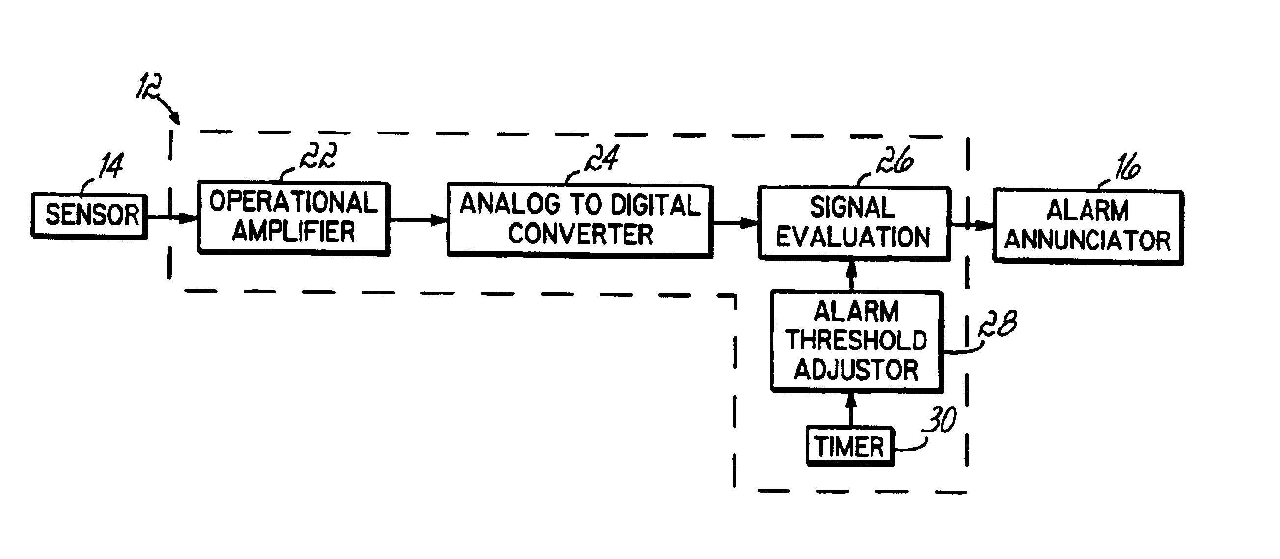
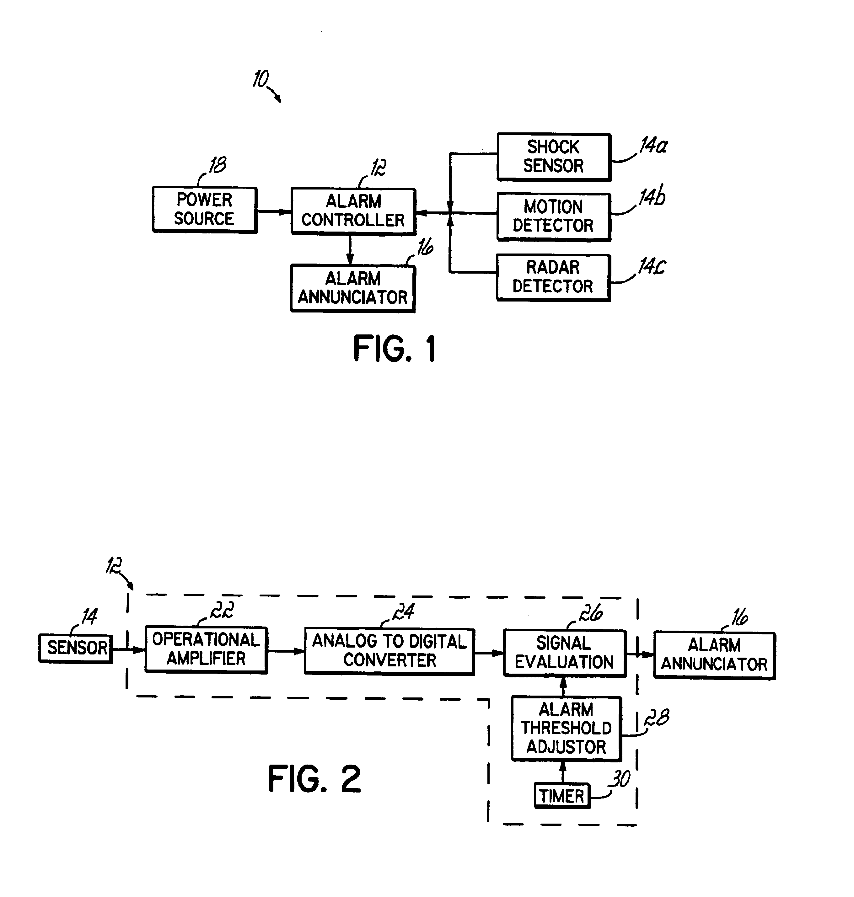
[0021]A block diagram of an alarm system 10 incorporating the present invention is shown in FIG. 1. That system 10 includes an alarm controller 12 that is coupled to a shock sensor 14a, a motion detector 14b, and a radar detector 14c. The alarm controller 12 is also coupled to an alarm annunciator 16 which emits an alarm in response to an alarm signal from the alarm controller 12. The alarm emitted by the alarm annunciator 16 may be a siren, bell, vocal command, chirp, beep, warning light, or the like, or any combination thereof. The alarm controller 12 receives its power from a power source 18 which, in a vehicle, is typically the vehicle's battery, or, in a home or business, is typically the standard household current. The power source 18 may also include a backup battery source in the event a vehicle's main battery is inoperative or household current is unavailable for a building's alarm system. The use of a backup battery or rechargeable super capacitor is typically done to avoi...


PUM


Abstract

An alarm system having the capability to self-adjust or self-calibrate itself is disclosed. The system includes an alarm controller and at least one sensor that generates a signal that corresponds to the magnitude of a detected event. The signal evaluator is part of the alarm controller and receives the magnitude signal from the sensor. The signal evaluator compares the magnitude signal to a user-defined or preset alarm sensor sensitivity threshold and generates an alarm signal if the magnitude signal exceeds the alarm signal sensitivity threshold. If repeated alarm signals are generated, an alarm threshold adjuster will adjust the sensor sensitivity threshold to a point where repeated magnitude signals will be ignored. The system will reset itself to the original user-defined or preset sensor sensitivity threshold levels after a predetermined time of no alarm signal generation. The alarm signals generated will activate an alarm annunciator, which generates an alarm.

Description

CROSS REFERENCE[0001]The present application claims benefit of U.S. provisional application Ser. No. 60 / 438,140, filed Jan. 6, 2003, the disclosure of which is hereby incorporated herein by reference in its entirety.FIELD OF THE INVENTION[0002]The present invention relates to alarm systems generally and, more particularly, to vehicle alarm systems.BACKGROUND OF THE INVENTION[0003]Alarm systems for installation in homes, businesses, or in movable vehicles such as automobiles are well known. These systems typically include an alarm controller that is coupled to an alarm annunciator and sensors located throughout the property or vehicle for detecting specific events indicative of a security violation. The alarm controller typically includes a microprocessor or microcontroller with sufficient memory and input / output (I / O) interface devices to effectively couple the controller to the sensors. Home or business alarm systems are typically powered from the standard household current, wherea...

Claims


Application Information

Patent Timeline
IPC IPC(8): B60R25/10G08B13/16G08B29/00G08B29/26
CPCB60R25/1004G08B13/1654G08B29/26
Inventor HANOOD, SCOTT T.
Owner JBS TECH
Why Eureka
Try Eureka