
Image display device

a display device and image technology, applied in the field of image display devices, can solve the problems of difficult to obtain a sharp display, difficult to display a sharp image, risk of white liquid leakage from the display media, etc., to prevent deterioration of display quality, prevent deterioration of display sharpness and display contras

Inactive Publication Date: 2005-10-18
E INK CORPORATION
View PDF13 Cites 24 Cited by
  • Summary
  • Abstract
  • Description
  • Claims
  • Application Information

AI Technical Summary

Benefits of technology

[0019]The present invention has been achieved in view of the above-mentioned problems, and an object thereof is to provide an image display device capable of preventing deterioration of display sharpness and display contrast even when displaying an image of high resolution, and capable of preventing a deterioration of display quality.

Problems solved by technology

Among these image display media, although the thermal rewritable display medium, the liquid crystal display medium having a memory property, and the like have excellent image memory property, they cannot provide a background with sufficient whiteness like paper, and thus the contrast between an image part and a non-image part is small when displaying an image, so that it has been difficult to display a sharp image.
Therefore, the contrast between the display part and the non-display part is lowered, so it has been difficult to obtain a sharp display.
Moreover, since the white liquid is sealed in these display media, there is a risk of leakage of the white liquid from the display media when the display media are detached from image display devices and handled in a rough manner like paper.
However, according to this method, it is difficult to completely rotate the particles and the contrast is deteriorated for particles without complete rotation, so a sharp display image is hard to form.
Furthermore, even in the case the half spherical surfaces painted in white can completely align on the display side, it is difficult to provide a white display like paper, due to light absorption and light scattering in the cavities, and consequently it has been difficult to obtain a sharp display image.
Moreover, since the particle size is required to be smaller than a pixel size, a problem is involved in that fine spherical particles painted in colors need to be produced for a high resolution display, so a highly sophisticated production technique is required.
Moreover, since the display medium only contains solids, a problem of liquid leakage cannot occur.
However, in the above-mentioned display medium disclosed in Japanese Patent Application No. 2000-165138, when a simple matrix drive with linear electrodes provided at the display substrate and the rear substrate is used, since the particles are moved along the spread of the electric field generated between the substrates, the particles cannot be moved perpendicularly with respect to the substrates.
When an image with a low resolution of about several tens of dpi (dots per inch), this is in the degree of having image edge parts slightly blurred, and thus does not provide a significant influence visibly.
However, when an image with a high resolution exceeding 100 dpi, blurring and distortion of the image are conspicuous and drastically deteriorate the display quality.
When an image with a low resolution of several tens of dpi or less, this is again in the degree of having the image edge parts slightly blurred, and does not provide a significant influence visibly.
However, when an image of a high resolution exceeding 100 dpi, density deterioration of a dot image, line image, character image, or the like remarkably deteriorates the display quality.
Accordingly, although a good image with high contrast and without conspicuous particle spread can be obtained when a low resolution is used, a problem is involved of thickening of a line image along the linear electrodes formed on the rear substrate, and the line density deterioration becomes remarkable when a higher resolution is used, so as to deteriorate the display quality.
However, if the resolution of the display medium is higher, the particles cannot move perpendicularly with respect to a selected pixel electrode, and thus a problem is involved in that blurring and density deterioration of display dots become conspicuous, so as to deteriorate the display quality.

Method used


Image

  • Image display device
  • Image display device
  • Image display device

Examples


first embodiment

(First Embodiment)

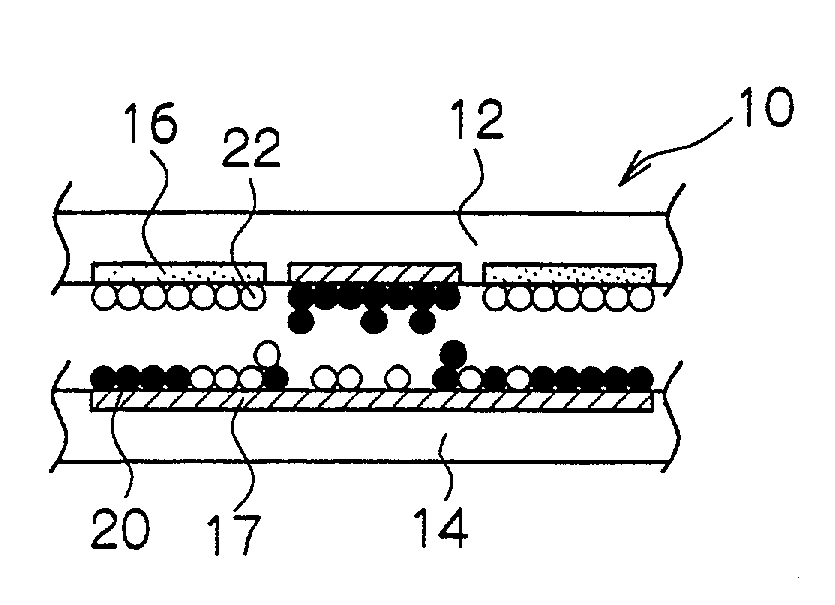
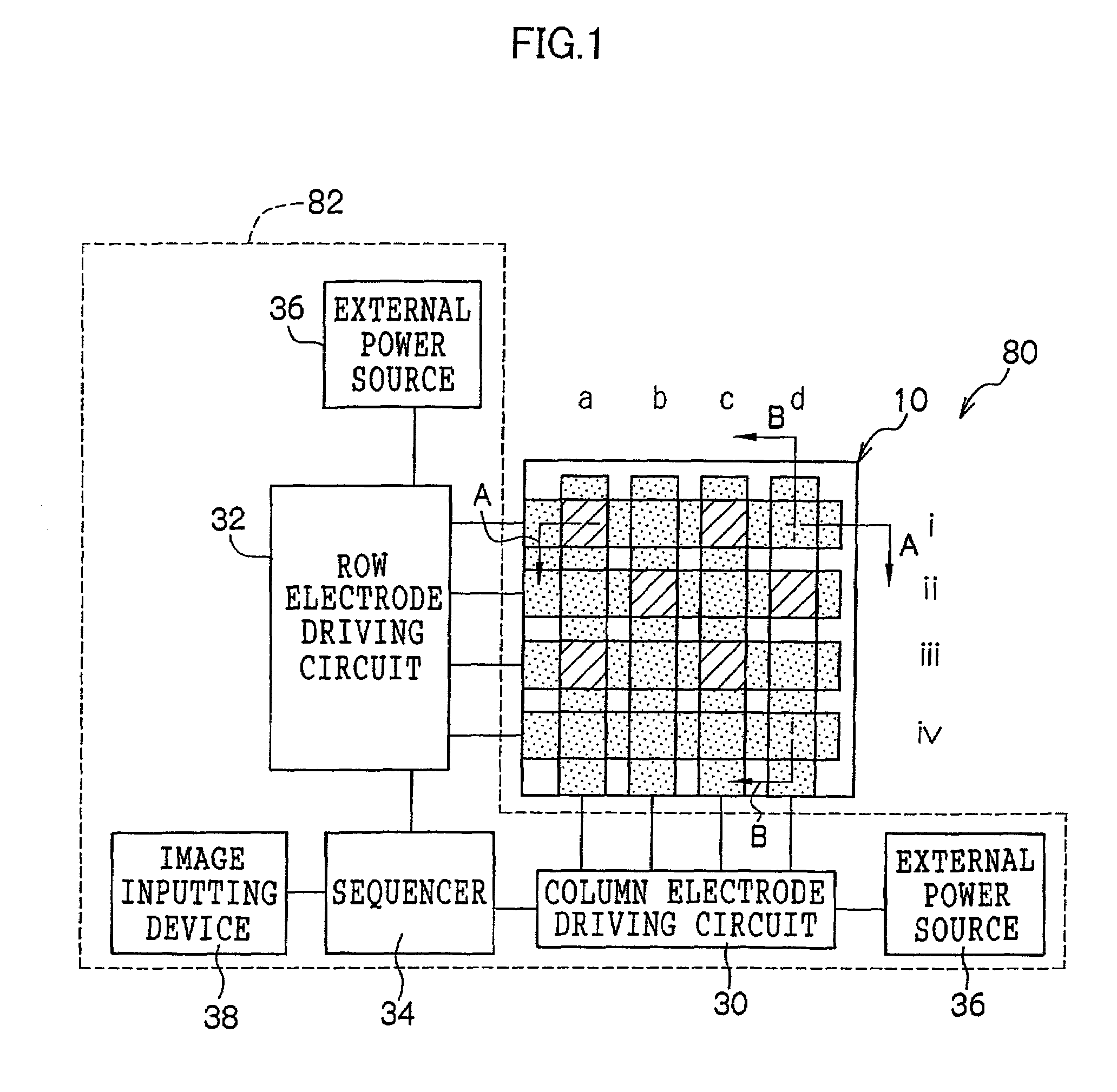
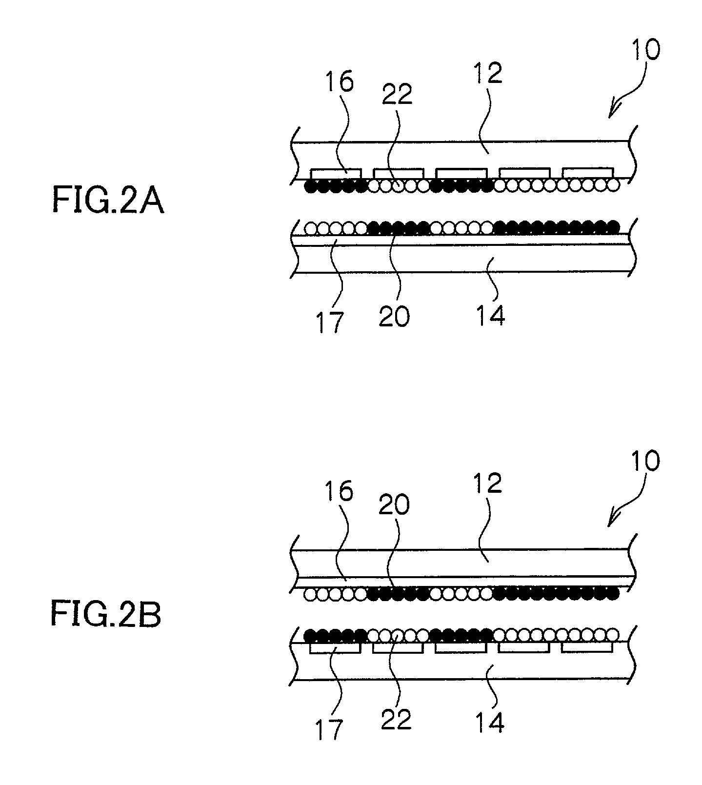
[0074]FIGS. 1 to 3B show an image display medium 10 according to this embodiment. As shown in FIGS. 1 to 3B, an image display device 80 comprises the image display medium 10 and a driving device 82 for driving the image display medium 10. The image display medium 10 comprises a transparent display substrate 12 disposed on an image display side, and a rear substrate 14 facing the display substrate 12 with a predetermined gap provided therebetween.

[0075]The image display medium 10 is to be driven by the so-called simple matrix driving method. As shown in FIGS. 3A and 3B, a plurality of linear electrodes (column electrodes) 16 (hereinafter referred to as “column electrodes”) are provided on the surface of the display substrate 12 facing the rear substrate 14. Similarly, a plurality of linear electrodes (row electrodes) 17 (hereinafter referred to as “row electrodes”) are provided on the surface of the rear substrate 14 facing the display substrate 12. The display subs...

second embodiment

(Second Embodiment)

[0102]Hereinafter, a second embodiment of the present invention will be explained.

[0103]Since the image display device of this embodiment has the same configuration as that of the above-mentioned image display device, explanation thereof is not provided. Only the driving embodiment of the driving device, that is, the behavior of the particles in the image display medium 10, will be explained.

[0104]FIGS. 10A to 10F show the behavior of the particles in this embodiment in the time series order. Similarly to FIGS. 6A to 6F and FIGS. 7A to 7F, FIGS. 10A to 10F show the behavior of the particles in the B—B cross-sectional view (see FIG. 2B) of the image display medium shown in FIG. 1 as an example of executing the black pixel display (dot display) from the white display state shown in FIG. 10A.

[0105]In this embodiment, first, as shown in FIG. 10B, a voltage VLP2 that moves the particles between the adjacent row electrodes without moving the particles between the substr...

third embodiment

(Third Embodiment)

[0109]Hereinafter, a third embodiment of the present invention will be explained. In this embodiment, the same numerals are provided for the same parts as those in the above-mentioned first embodiment and second embodiment and further explanation is not given therefor.

[0110]An image display device 84 according to this embodiment is shown in FIGS. 11, 12A and 12B. The image display device 84 comprises an image display medium 50 and a driving device 86 for driving the same. The image display medium 50 is to be driven by the so-called active matrix driving method. A uniform electrode 24 (hereinafter referred to as the plane electrode 24) is provided on the surface of the display substrate 12 facing the rear substrate 14. Moreover, a plurality of electrodes 25 (hereinafter referred to as the pixel electrodes 25) are provided on the surface of the rear substrate 14 facing the display substrate 12, corresponding to each pixel.

[0111]Moreover, as shown in FIG. 11, in this ...


PUM

PropertyMeasurementUnit
distanceaaaaaaaaaa
distanceaaaaaaaaaa
voltageaaaaaaaaaa

Abstract

The present invention is for providing an image display device capable of preventing deterioration of display sharpness and contrast, and capable of improving display quality. An image display medium has a display substrate, having a first electrode, disposed on an image display surface side, a rear substrate having a plurality of second electrodes facing the display substrate, and two kinds of particle groups having different colors and charge characteristics sealed between the display substrate and the rear substrate movably between the first electrode and the second electrodes by an electric field. Before application of a display drive voltage for executing the image display, a voltage is applied to the image display medium by a voltage applying component so as to generate an electric field for moving the particle groups between the second electrodes to adjacent the second electrodes.

Description

BACKGROUND OF THE INVENTION[0001]1. Field of the Invention[0002]The present invention relates to an image display device. More specifically, it relates to an image display device for repeatedly displaying images by driving colored particles sealed between a transparent display substrate and a rear substrate by an electric field.[0003]2. Description of the Related Art[0004]Conventionally, as an image displaying medium (display device) capable of being rewritten repeatedly, a twisting ball display (two-color-painted particle rotating display), an electrophoresis display medium, a magnetophoresis display medium, a thermal rewritable display medium, a liquid crystal display medium having a memory property, and the like have been proposed.[0005]Among these image display media, although the thermal rewritable display medium, the liquid crystal display medium having a memory property, and the like have excellent image memory property, they cannot provide a background with sufficient whiten...

Claims


Application Information

Patent Timeline
Patent Type & Authority Patents(United States)
IPC IPC(8): G09G3/34G02F1/17G02F1/167
CPCG09G3/2085G09G3/344G02F1/167G09G2300/0439G09G2300/0473G09G2300/06G09G2310/0248G09G2310/061G09G2320/02G09G2320/0209G09G2300/08G09G2310/068
Inventor MACHIDA, YOSHINORIMATSUNAGA, TAKESHISHIGEHIRO, KIYOSHIYAMAGUCHI, YOSHIROSUWABE, YASUFUMISAKAMAKI, MOTOHIKO
Owner E INK CORPORATION
Learn More