Shape-intrinsic watermarks for 3-D solids

a watermark and shape technology, applied in the field of shape-intrinsic watermarks for 3d solids, can solve the problems of watermark destruction and the object cannot be considered to be approximately identical to the original obj

Inactive Publication Date: 2005-10-18
MASSACHUSETTS INST OF TECH
View PDF5 Cites 18 Cited by
  • Summary
  • Abstract
  • Description
  • Claims
  • Application Information

AI Technical Summary

Benefits of technology

[0057]The proposed method will be useful to help protect ownership of expensive digital data models of an original solid model when it is officially registered with an acknowledged a...

Problems solved by technology

Such watermarks are destroyed only if the digital model describing the shape is changed so much that t...

Method used


Image

  • Shape-intrinsic watermarks for 3-D solids
  • Shape-intrinsic watermarks for 3-D solids
  • Shape-intrinsic watermarks for 3-D solids

Examples


examples

[0132]FIG. 4A illustrates an example using the present invention to compare two surfaces, A 150 and B 152. The lines drawn in these figures provide a perspective view of each surface 150, 152, and are not indicative of the principal lines of curvature. That is, the wireframes illustrated in these figures are not intrinsic to the surfaces, and may depend on parameterization of the surfaces.

[0133]FIG. 4B illustrates the same surfaces A 150 and B 152 as FIG. 4A, with control points indicated. The control points together with knot vectors define B-spline surfaces. FIG. 4B clearly shows that the same shape can be expressed by different sets of control points. Some methods for watermarking hide information in the control points. This information can be easily lost by using a different set of control points.

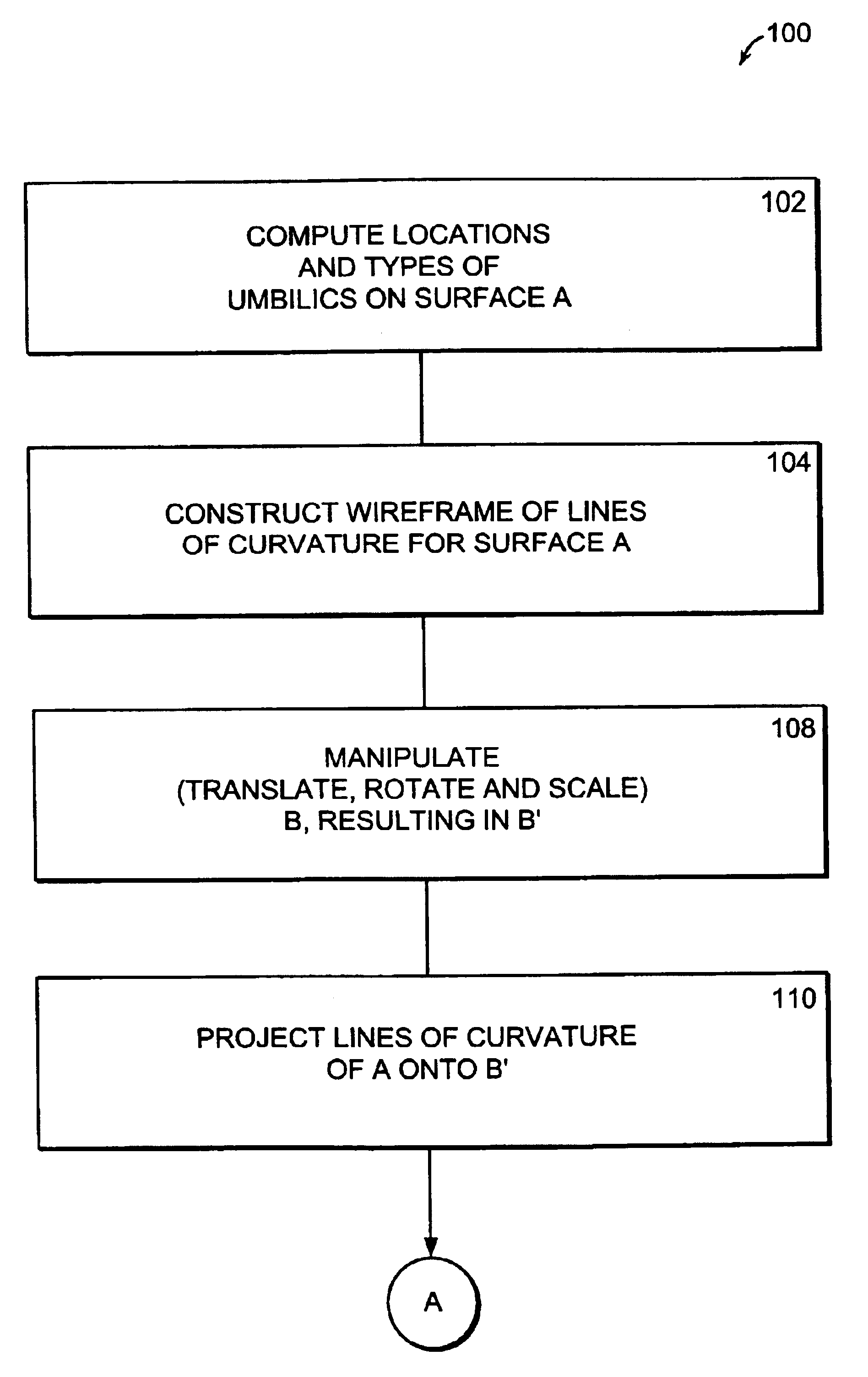
[0134]FIGS. 4C through 4E illustrate the various transformations performed on surface B in step 108 of FIG. 3A. In FIG. 4C, surface B is translated, as indicated by arrow 156, such that...


PUM


Abstract

Umbilics of two surfaces are compared and it is determined from this comparison whether the suspect surface is a copy of the original surface based on the comparison. Comparing umbilics includes determining whether locations of the umbilics of the suspect surface match within a specified margin umbilics of the original surface, and determining whether pattern types of umbilics of the suspect surface match pattern types of corresponding umbilics of the original surface. A “weak” test may be performed, in which corresponding points on the two surfaces are compared, wherein the comparison of umbilics is performed if corresponding points of the two surfaces are located within a specified margin of each other. The points may be gridpoints on wireframes, which in turn may be based on lines of curvature of the surfaces. Comparing umbilics is performed if it is determined that each surface has at least one umbilic. Further still, an “intermediate” test may be performed which includes, for each surface, computing the principal directions of lines of curvature at each grid point. The computed directions of lines of curvature for corresponding gridpoints on the surfaces are compared. A determination is made as to whether the suspect surface is a copy of the original surface, based on the comparison.

Description

RELATED APPLICATION(S)[0001]This application is a continuation of a U.S. application Ser. No. 10 / 040,960 filed Jan. 7, 2002, entitled “SHAPE-INTRINSIC WATERMARKS FOR 3-D SOLIDS”, by Takashi Maekawa, Nicholas M. Patrikalakis, Franz-Erich Wolter and Hiroshi Masuda.[0002]The entire teachings of the above application are incorporated herein by reference.GOVERNMENT SUPPORT[0003]The invention was supported, in whole or in part, by a grant DMI-0010127 from the National Science Foundation. The Government has certain rights in the invention.BACKGROUND OF THE INVENTION[0004]As the information age has rapidly progressed, the relative contributions of different components defining our economies have also changed. For example, in our modern society, economic value creation is no longer created only by the fabrication of physical objects, but is created also within the context of information exchange. An essential initial part of the effort needed to fabricate physical objects lies in such creati...

Claims


Application Information

Patent Timeline
IPC IPC(8): G06T1/00
CPCG06T1/0064G06T2201/0051
Inventor MAEKAWA, TAKASHIPATRIKALAKIS, NICHOLAS M.WOLTER, FRANZ-ERICHMASUDA, HIROSHI
Owner MASSACHUSETTS INST OF TECH
Why Eureka
Try Eureka