Calibration method and device for robot hole forming platform vision measurement system

A robotic hole-making and visual measurement technology, applied in automatic control devices, feeding devices, measuring/indicating equipment, etc., can solve problems such as large errors

Active Publication Date: 2014-08-20
ZHEJIANG UNIV
View PDF4 Cites 47 Cited by
  • Summary
  • Abstract
  • Description
  • Claims
  • Application Information

AI Technical Summary

Problems solved by technology

Literature (Zhu Zhenyou, Xu Aijie, Lin Tao, etc. "hand-eye" relationship fast calibration algorithm for robot vision [J]. Optical Technology, 2004, 30 (2): 150-152.) Obtaining signs through robot-defined multi-

Method used


Image

  • Calibration method and device for robot hole forming platform vision measurement system
  • Calibration method and device for robot hole forming platform vision measurement system
  • Calibration method and device for robot hole forming platform vision measurement system

Examples


Embodiment Construction

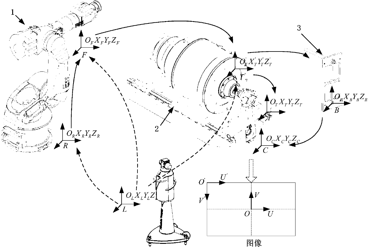
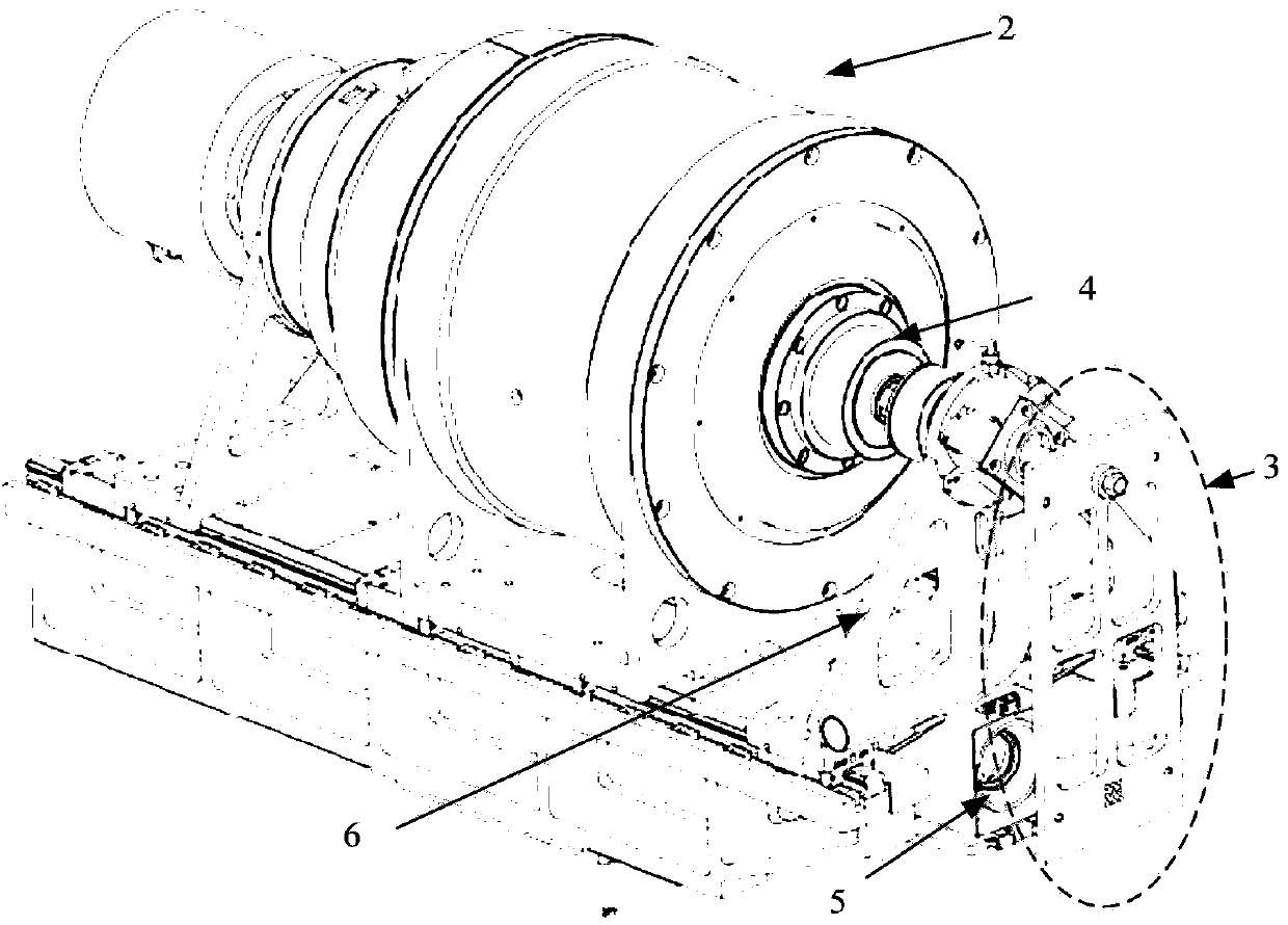
[0073] like figure 1 and figure 2 As shown, a calibration device for the visual measurement system of the robot hole-making platform, the calibration device 3 is installed on the end effector 2 of the hole-making robot 1, the hole-making tool is mounted on the main shaft 4 of the end effector 2, and The end effector 2 is provided with a camera 5 facing the calibration device 3; figure 1 The hole-making robot 1, end effector 2, and calibration device in the figure have unequal drawing scales, and the size of the device in the picture is not used to limit the actual device. This figure is only used to illustrate the positional relationship of each coordinate system.

[0074] According to the structure and size of the helical milling end effector 2 used in the present invention, combined with the functional requirements to realize the camera calibration and hand-eye calibration, the processing and design are as follows: image 3 The calibration device 3 shown includes a spindl...


PUM


Abstract

The invention discloses a calibration device for a robot hole forming platform vision measurement system, and further discloses a calibration method based on the calibration device. The method comprises the steps of building a calibration plate coordinate system and a tool coordinate system according to a calibration plate, building a two-dimensional transformation relation of the calibration plate coordinate system and the tool coordinate system on a calibration plate locking face according to the geometric positional relation of a middle hole and a spindle hole of a none-hole array, building a camera coordinate system on a calibration plate shooting face, conducting calibration on camera intrinsic parameters and calculation on camera external parameters according to a nine-hole array image shot by a camera, building a two-dimensional transformation relation of the camera coordinate system and the calibration plate coordinate system on the calibration plate locking face, thereby obtaining a two-dimensional hand-eye relation of the camera coordinate system and the tool coordinate system on the calibration plate locking face, and then obtaining a three-dimensional hand-eye relation between the camera coordinate system and the tool coordinate system by combining distance information, obtained through measurement of a camera coordinate system original point in the hole forming depth direction with distance information, obtained through measurement, of a tool coordinate system original point.

Description

technical field [0001] The invention belongs to the field of manufacturing automation, and in particular relates to a calibration method and device for a robot hole-making platform vision measurement system. Background technique [0002] With the continuous improvement of the positional accuracy of industrial robot technology, the robot hole making system has become the best choice for flexible automation hole making in the aviation industry relying on its low investment and high flexibility. In the process of robot hole making, the error of the robot itself, the manufacturing and positioning errors of the workpiece, lead to the position error of the processed assembly hole. In order to make the position coordinates of the processed assembly holes adapt to the on-site assembly state of the workpiece, a series of reference holes are processed on the workpiece in advance, and then the vision system is used to locate the reference holes, and the deviation between the actual pos...

Claims


Application Information

Patent Timeline
IPC IPC(8): B23Q15/12B23Q17/00B25J13/08
CPCB23Q17/2414B25J11/005B25J13/08
Inventor 朱伟东曲巍崴毕运波柯映林
Owner ZHEJIANG UNIV
Why Eureka
Try Eureka