Method for correcting the beam intensity in an image recording apparatus using a multi-channel light modulator

a light modulator and beam intensity technology, applied in the field of image recording apparatus, can solve the problem that the signal of a single-element photodetector can be lost in the noise generated by light from unselected modulator elements, and achieve the effect of precise beam intensity calibration method

Inactive Publication Date: 2005-10-18
DAINIPPON SCREEN MTG CO LTD
View PDF19 Cites 37 Cited by
  • Summary
  • Abstract
  • Description
  • Claims
  • Application Information

AI Technical Summary

Benefits of technology

[0006]The present invention is intended for an image recording apparatus for recording an image on a recording medium, and an object of the present invention is to provide a precise beam intensity calibration method for a multi-channel recording apparatus.

Problems solved by technology

If a multi-channel light modulator has a low extinction rate(contrast), however, a signal from a single-element photodetector can be lost in the noise generated by light from unselected modulator elements.

Method used


Image

  • Method for correcting the beam intensity in an image recording apparatus using a multi-channel light modulator
  • Method for correcting the beam intensity in an image recording apparatus using a multi-channel light modulator
  • Method for correcting the beam intensity in an image recording apparatus using a multi-channel light modulator

Examples


Embodiment Construction

[0027]

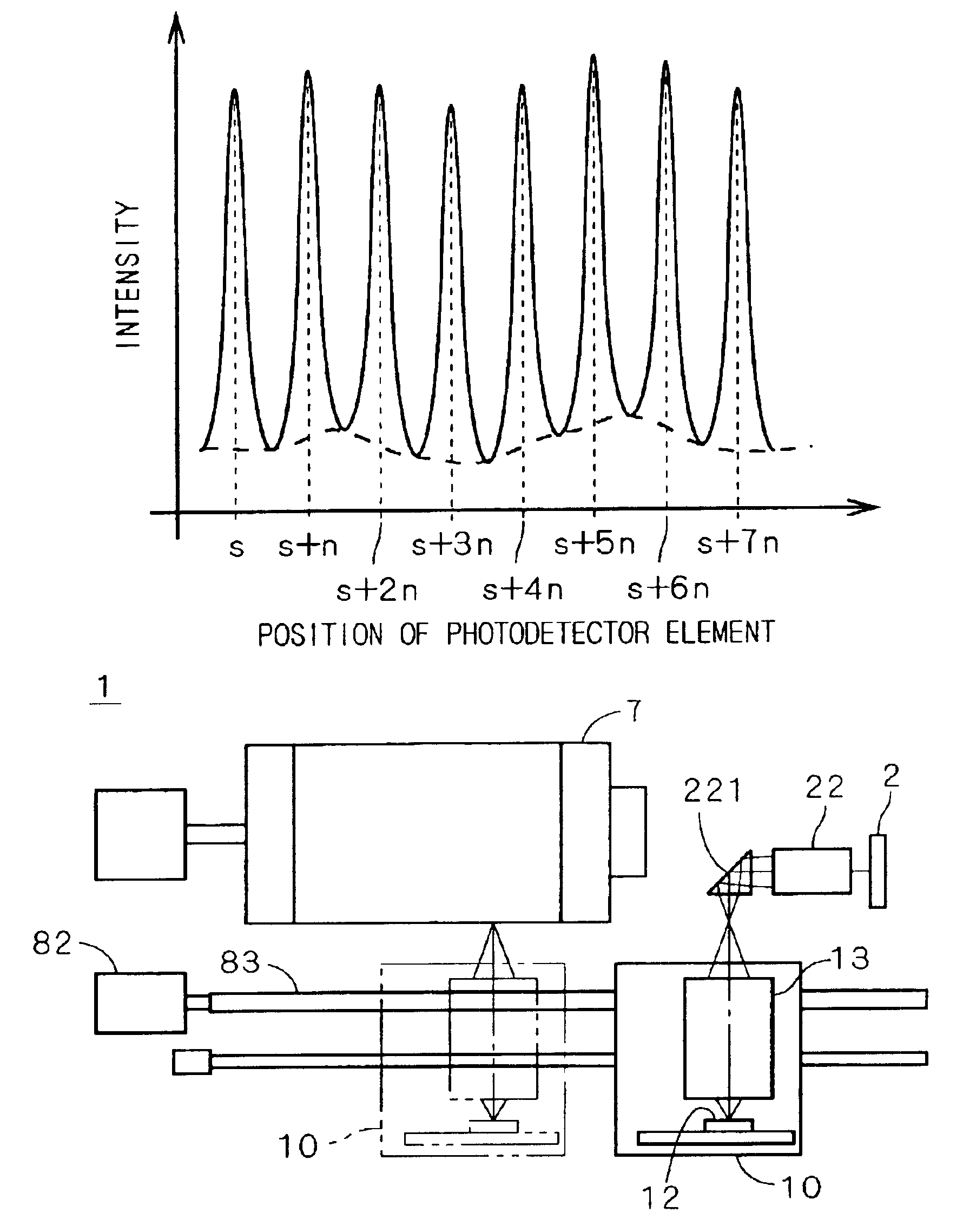
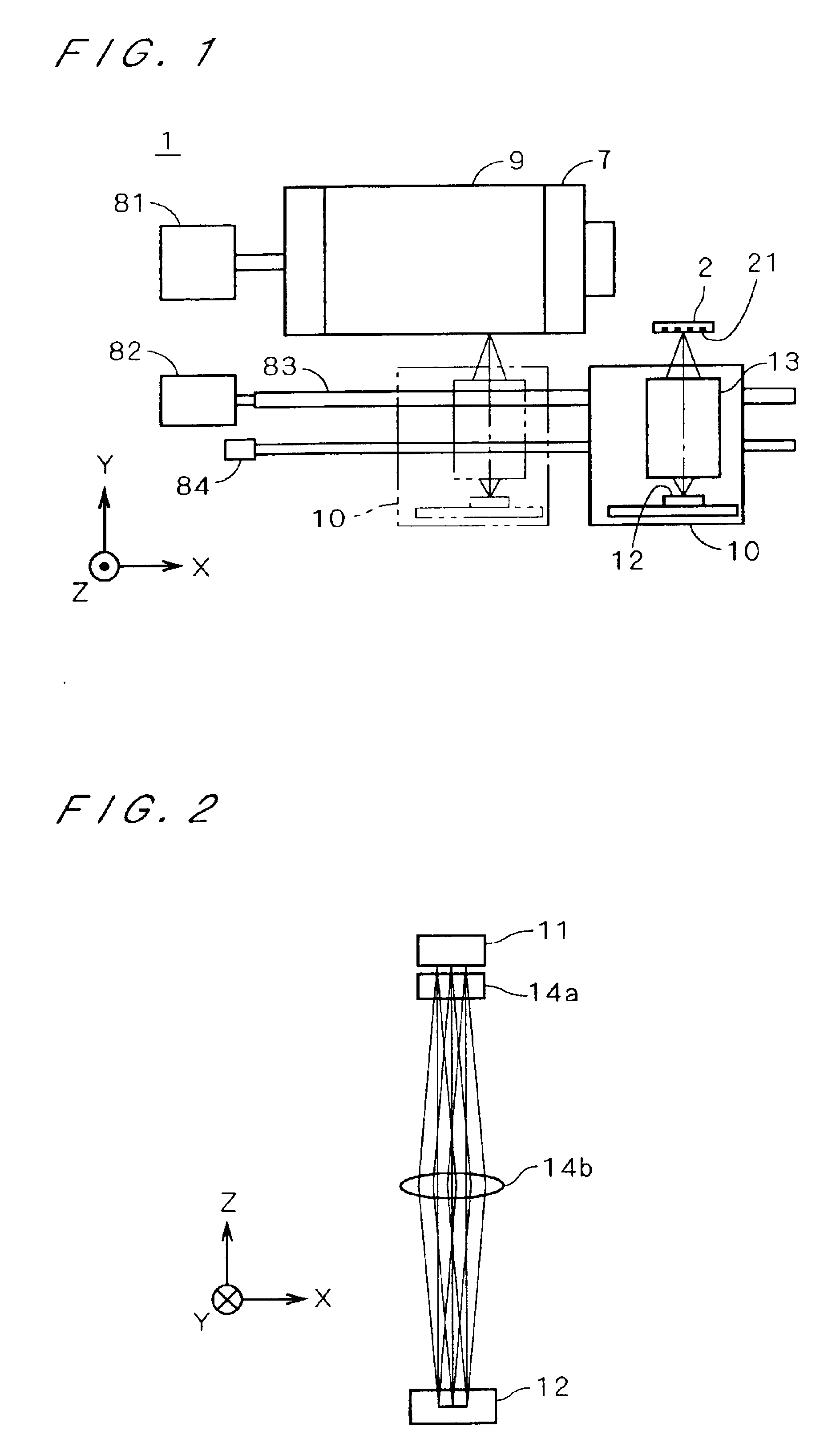
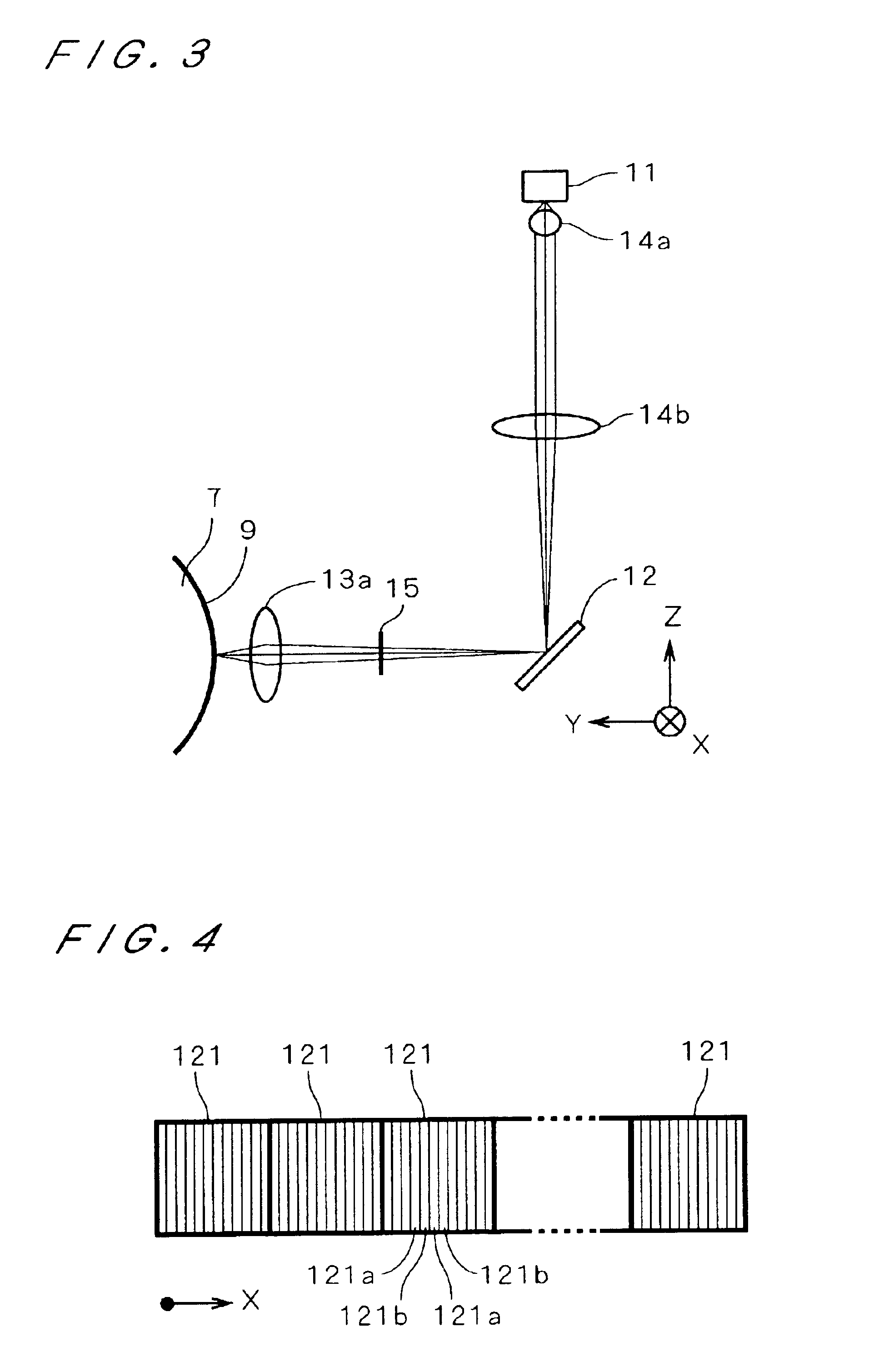
[0028]FIG. 1 is a view showing a constitution of an image recording apparatus 1 in accordance with a preferred embodiment of the present invention. In this figure, a light source is not shown. The image recording apparatus 1 has an optical head 10 for delivering writing beams and a holding drum 7 for holding a recording medium 9 on which an image is recorded by the writing beams. As the recording medium 9, for example, used are a printing plate, a film for forming the printing plate and the like. A photosensitive drum for plateless printing may be used as the holding drum 7 and in this case, it is understood that the recording medium 9 corresponds to a surface of the photosensitive drum.

[0029]The image recording apparatus 1 further has a photodetector 2 for correcting the writing beam intensity. In FIG. 1, the optical head 10 at a position for image recording is represented by a phantom line (two-dot chain line) and that at a position for correcting the beam intensity.

[0030]Th...


PUM

PropertyMeasurementUnit
distanceaaaaaaaaaa
photosensitiveaaaaaaaaaa
electric potentialaaaaaaaaaa

Abstract

In an image recording apparatus 1 which records an image on a recording medium 9 by moving an optical head 10 while rotating the recording medium 9 held by a holding drum 7, a photodetector 2 having a plurality of photodetector elements 21 is provided in a range of movement of the optical head 10. In correcting beam intensity, the optical head 10 is positioned so precisely that the photodetector 2 can receive the signal light beams. This constitution makes it possible to detect signal light beams from the light modulator with high S/N ratio as compared with a conventional case where one photodetector element sequentially receives the signal light beams, and therefore possible to correct the beam intensities with high accuracy.

Description

BACKGROUND OF THE INVENTION[0001]1. Field of the Invention[0002]The present invention relates to an image recording apparatus which uses a multi-channel light modulator, more specifically calibration of the beam intensity.[0003]2. Description of the Background Art[0004]Use of a multi-channel light modulator well known in the art of image recording. Such a light modulator is illuminated by light from a light source and creates multiple writing beams. To ensure high image quality, each writing beam is required to have a same target intensity. A conventional method for this purpose is to calibrate all writing beams in accordance with signals from a single-element photodetector.[0005]If a multi-channel light modulator has a low extinction rate(contrast), however, a signal from a single-element photodetector can be lost in the noise generated by light from unselected modulator elements. Provided a modulator has 500 elements with a contrast of 100:1, total beam intensity of the unselected...

Claims


Application Information

Patent Timeline
Patent Type & Authority Patents(United States)
IPC IPC(8): G06K15/12H04N1/40B41J2/44G03F7/24
CPCG06K15/1214G06K15/1266H04N1/40025
Inventor KATAOKA, YOSHIKAZUTAMAKI, EIICHIHIRAWA, TAKAHIDE
Owner DAINIPPON SCREEN MTG CO LTD
Why Eureka
Try Eureka