
Methods for improving contrast based dynamic range management

Inactive Publication Date: 2005-10-18
GENERAL ELECTRIC CO
View PDF15 Cites 5 Cited by
  • Summary
  • Abstract
  • Description
  • Claims
  • Application Information

AI Technical Summary

Problems solved by technology

One of the fundamental image processing problems in digital x-ray imaging is the need to transform the intensity dynamic range of the input image to the dynamic range supported by an available display device.

Method used


Image

  • Methods for improving contrast based dynamic range management
  • Methods for improving contrast based dynamic range management
  • Methods for improving contrast based dynamic range management

Examples


Embodiment Construction

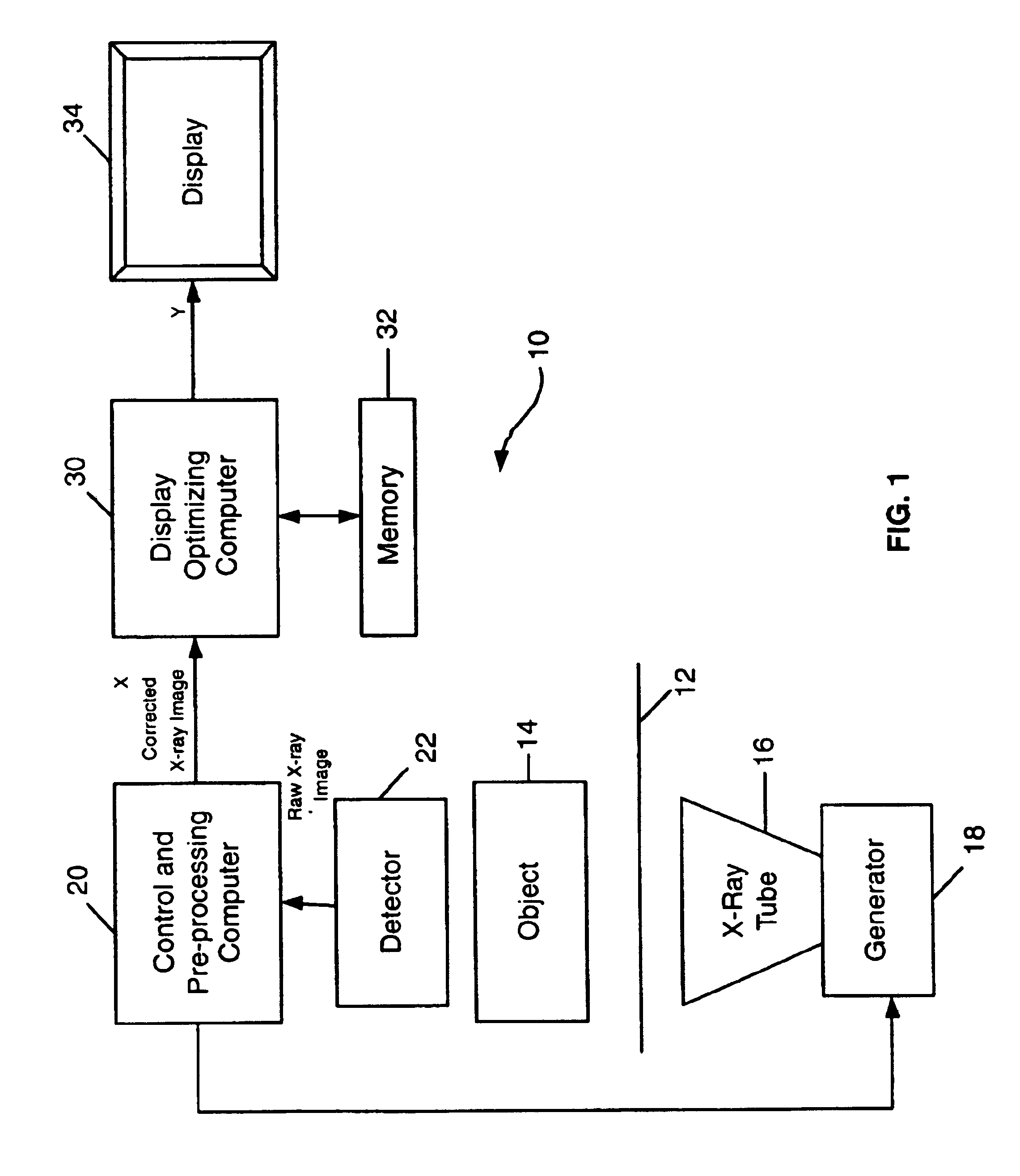
[0015]FIG. 1 is a schematic flow diagram of an x-ray imaging system 10 which can implement and perform the C-DRM processing algorithm of the invention. System 10 includes a table 12 on which an object 14 is placed prior to being imaged (e.g., a human body). Object 14 is irradiated by x-rays emitted by an x-ray tube 16, driven by a generator 18 under exposure management control by a control and preprocessing computer 20. X-rays passing through the object 14 are attenuated in differing amounts depending upon the character of the body portions, and conditions therein, of the object 14 being imaged. Thus, the variously attenuated x-rays impinge upon and are detected by an image detector 22, the image signal output of which is supplied to the control and preprocessing computer 20, all in conventional fashion. The image detector 22 may be a digital detector or an analog detector. In use, an analog detector is coupled with a pick up tube or CCD resulting in a digital imager. As is likewise...


PUM


Abstract

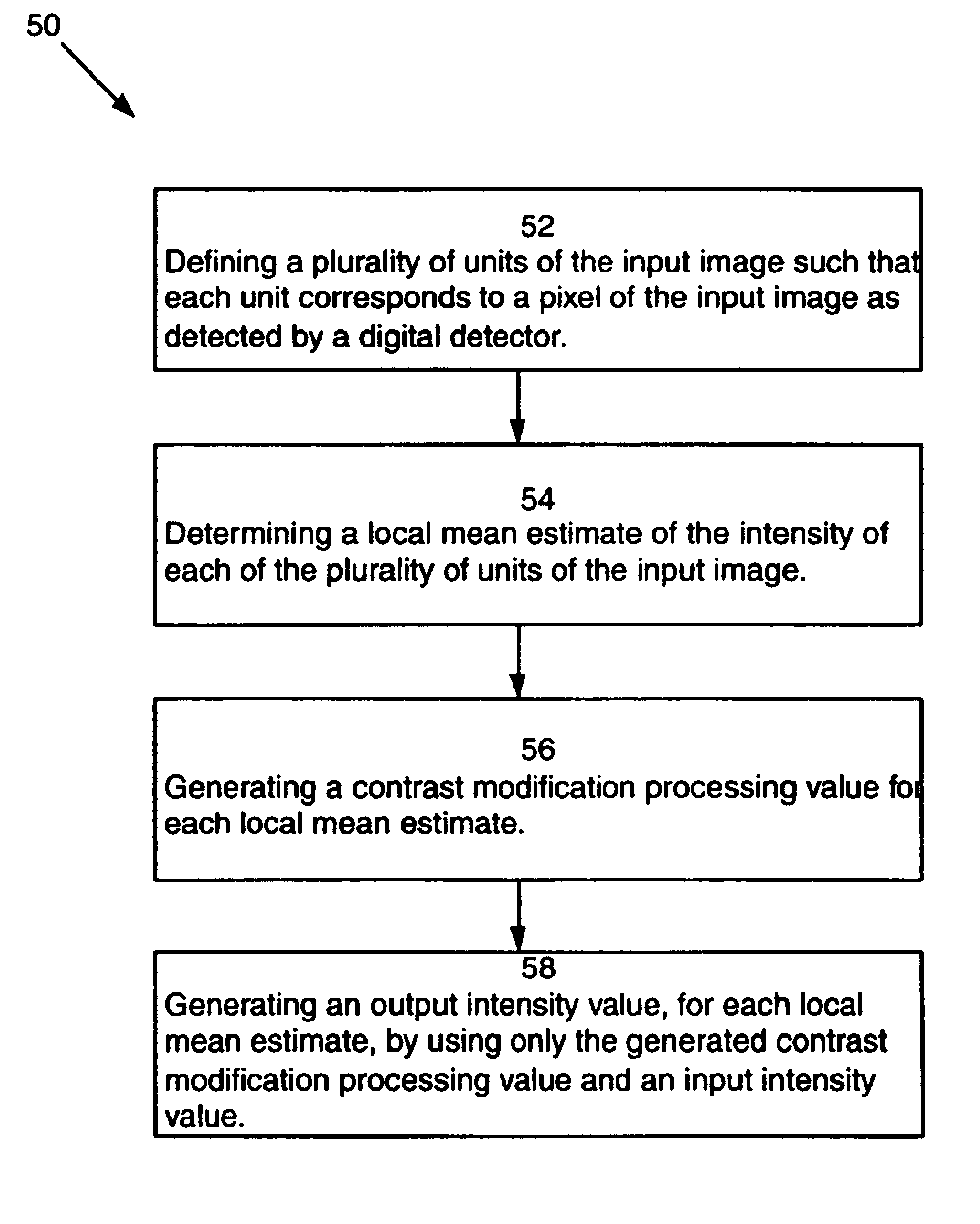
A method for compressing an intensity dynamic range of an input image to a reduced intensity dynamic range of an image display device includes defining a plurality of units of the input image, determining a local mean estimate of an intensity of each of the plurality of units of the input image, generating a contrast modification processing value for each local mean estimate, and generating an output intensity value, for each local mean estimate, by using only the generated contrast modification processing value and an input intensity value.

Description

BACKGROUND OF INVENTION[0001]This invention relates generally to contrast-based dynamic range management (C-DRM), and more particularly to a method, a related memory medium, and an apparatus for implementing and performing a contrast-based dynamic range management algorithm.[0002]Digital x-ray imaging is a well-known, non-contact technique for observing, in real time, interior aspects of an object. In practice, an x-ray beam is generated and targeted on an object of interest. A detecting device is positioned on the other side of the object and detects the x-rays transmitted through the object. The detected x-ray signals are converted to digital signals that represent various features in the object, are further processed, and the resulting signal is displayed on an image display device such as a CRT.[0003]One of the fundamental image processing problems in digital x-ray imaging is the need to transform the intensity dynamic range of the input image to the dynamic range supported by a...

Claims


Application Information

Patent Timeline
IPC IPC(8): G06T5/20
CPCG06T5/20H04N5/32H04N23/30
Inventor LANGAN, DAVID ALLENLIENARD, JEAN
Owner GENERAL ELECTRIC CO
Learn More