Solid state light source

a light source and solid state technology, applied in the direction of cycle equipment, instruments, lighting support devices, etc., can solve the problems of halogen lamps consuming 150 watts of power, generating a tremendous amount of heat, and a typical source is not a sealed, shock-resistant uni

Inactive Publication Date: 2005-10-25
LED PIPE
View PDF45 Cites 127 Cited by
  • Summary
  • Abstract
  • Description
  • Claims
  • Application Information

AI Technical Summary

Benefits of technology

[0014]The light source according to the present invention may include a plurality of colors of LED elements in the LED array. The light source may have the LED array divided into channels of LED element pairs operated simultaneously. The light source may use 5 mm LED elements in the LED array, although other sizes and

Problems solved by technology

However, the typical halogen source suffers several shortcomings and was not designed for use on the factory floor.
The light from a fresh halogen lamp is brilliant; but, output declines steadily over the lamp's relatively short 1000 hour life.
In addition, a typical halogen lamp consumes 150 watts of power and generates a tremendous amount of heat.
Consequently, the typical source is not a sealed, shock resistant unit because ventilation is required.
Due to these design considerations

Method used


Image

  • Solid state light source
  • Solid state light source
  • Solid state light source

Examples


Embodiment Construction

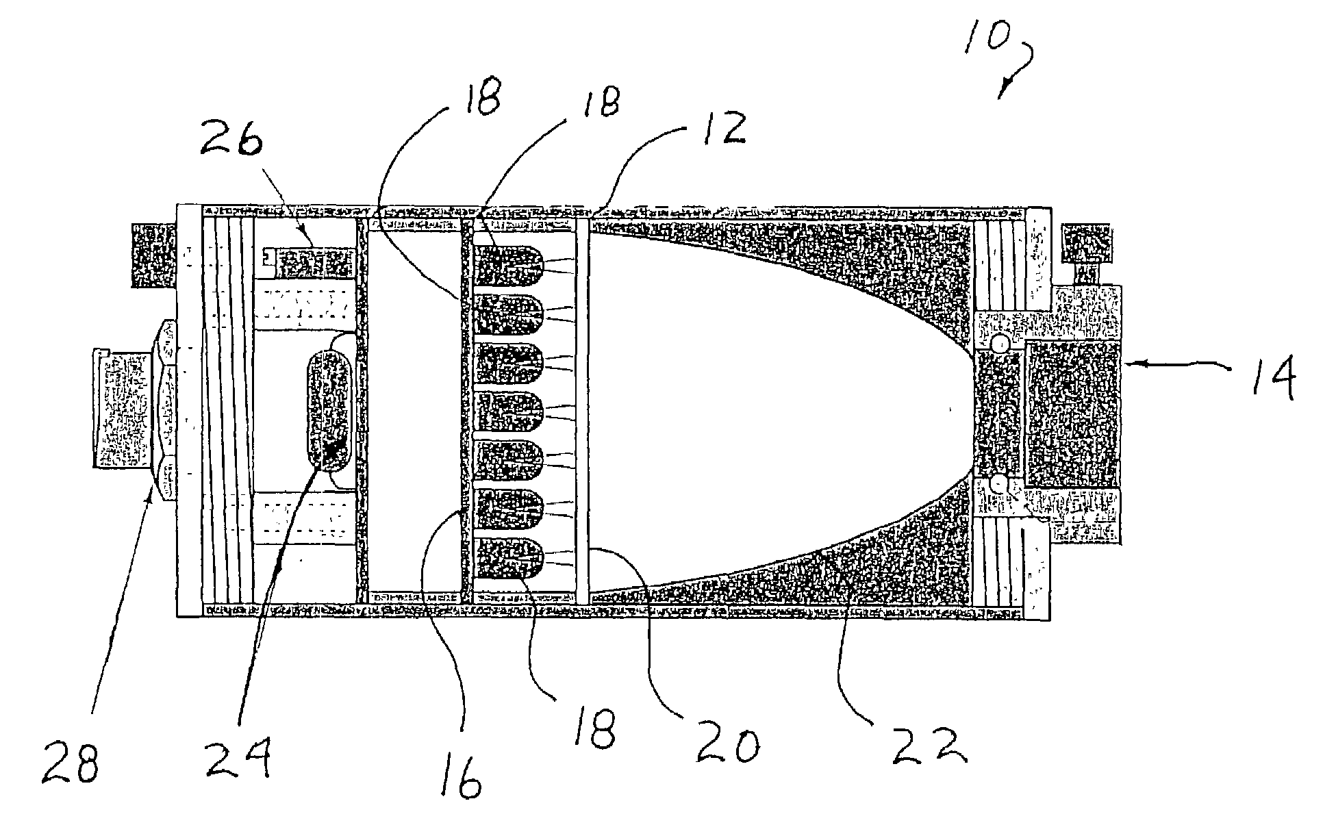
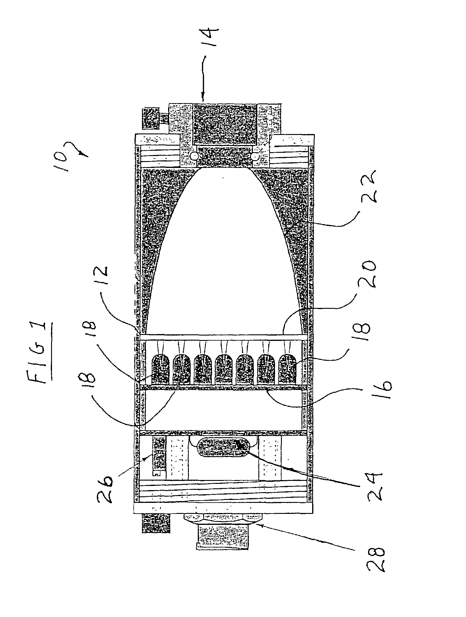
[0020]One embodiment of the present invention is shown in FIGS. 1–2. As shown in FIG. 1, the present invention is a light source 10 for illuminating a fiber optic bundle (not shown) such as used in machine vision illumination. The light source 10 includes a rigid, substantially closed housing 12 formed of an anodized aluminum tube with threaded end caps. Other materials, such as plastic or steel, may also be used to form the housing 12. One end of the housing 12 includes a conventional fiber optic bundle coupling 14 for receipt of an end of a fiber optic bundle in a conventional manner. The housing 12 can easily accommodate different couplings 14 simply by replacing the end cap and coupling 14. This construction allows the light source 10 to be used with a variety of fiber optical bundles.

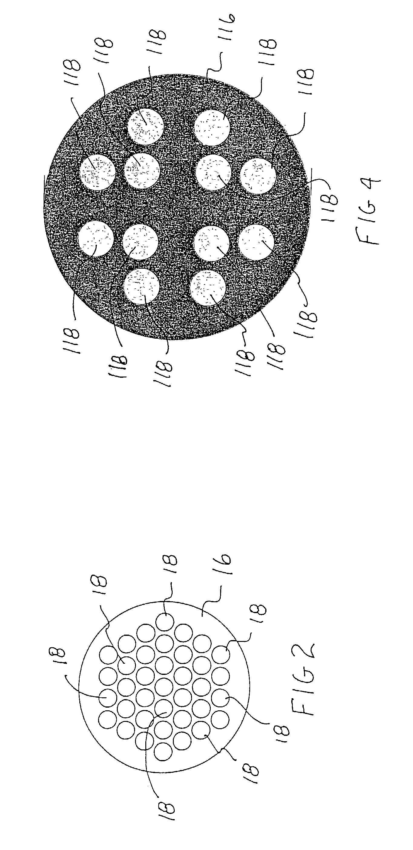
[0021]The light source 10 includes an LED array 16 formed of a plurality of individual LED elements 18 as shown in FIG. 2. The LED elements may be of a variety of colors. Preferably, the LED elemen...


PUM


Abstract

A light source includes a housing, an LED array of individual LED elements mounted in the housing, and a controller mounted in the housing and coupled to the LED array. The controller sequentially, intermittently pulses the LED elements of the LED array. The controller over drives the LED elements of the LED array with a current in excess of several times the continuous forward rating for the individual LED elements. The housing is a substantially closed, waterproof, tubular member and may include a power source in the housing. The light source may form a portable light source. The light source may include a fiber optic bundle coupling in the housing and a fresnel lens between the LED array and the fiber optic bundle coupling.

Description

RELATED APPLICATION[0001]This application claims the benefit of U.S. Pending Application Ser. No. 60 / 326,802 entitled “Solid State Light Source” Filed Oct. 3, 2001 which is incorporated herein by reference.BACKGROUND OF THE INVENTION[0002]1. Field of the Invention[0003]The present invention relates to a solid state light source, and more particularly, to a light source using an array of light emitting diodes elements (LED elements) arranged in a sealed housing.[0004]2. Brief Description of the Prior Art[0005]Specialized light sources have been developed in numerous industries. For example, light sources utilizing fiber optic bundles have been used by machine vision engineers for years to put light just where it is needed. Fiber enables the engineer the generate the precise lighting geometries required to perform difficult inspections. Halogen sources have been a mainstay to illuminate these fiber optic bundles. However, the typical halogen source suffers several shortcomings and was...

Claims


Application Information

Patent Timeline
IPC IPC(8): B62J6/02B62J6/00F21V21/08F21L4/00F21L4/02F21V21/06F21V21/088F21V8/00
CPCB62J6/02F21L4/027F21V21/0885F21V21/06F21V2200/17F21Y2101/02B62J6/029F21Y2115/10
Inventor PRITCHARD, DONALD V.MAGISKE, WILLIAM J.
Owner LED PIPE
Why Eureka
Try Eureka