Hybrid transmission

a transmission and hybrid technology, applied in the direction of electric generator control, machine/engine, gearing, etc., can solve the problems of increasing the axial length of the transmission, the difficulty of putting various parts of the speed change unit,

Inactive Publication Date: 2005-10-25
NISSAN MOTOR CO LTD
View PDF11 Cites 8 Cited by
  • Summary
  • Abstract
  • Description
  • Claims
  • Application Information

AI Technical Summary

Benefits of technology

[0009]It is therefore an object of the present invention to provide a hybrid transmission which is free of the above-mentioned shortcomings.

Problems solved by technology

However, the arrangement of that split section inevitably brings about a difficulty in putting various parts of the speed change unit in a deeper given limited space of the housing under assembling process of the transmission.
Furthermore, in the above-mentioned known transmission, the arrangement of the wiring from the motor / generator unit causes an increase in axial length of the transmission.

Method used


Image

  • Hybrid transmission
  • Hybrid transmission
  • Hybrid transmission

Examples


Embodiment Construction

[0016]In the following, a hybrid transmission of the present invention will be described in detail with the aid of the accompanying drawings.

[0017]For ease of description, various directional terms, such as, right, left, upper, lower, rightward and the like, are used in the description. However, such terms are to be understood with respect to a drawing or drawings on which the corresponding part or portion is shown.

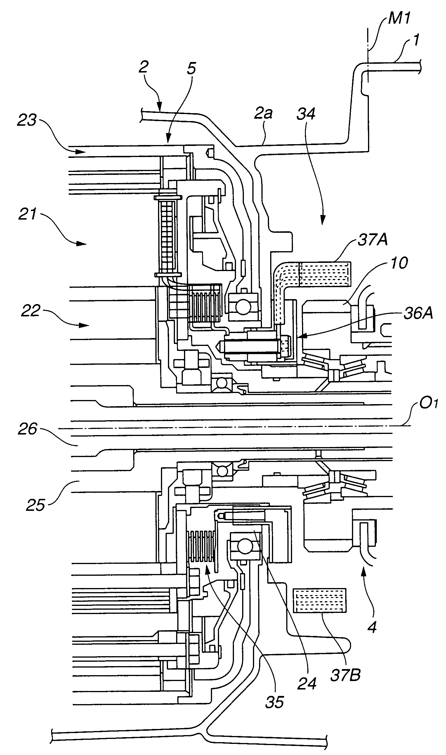
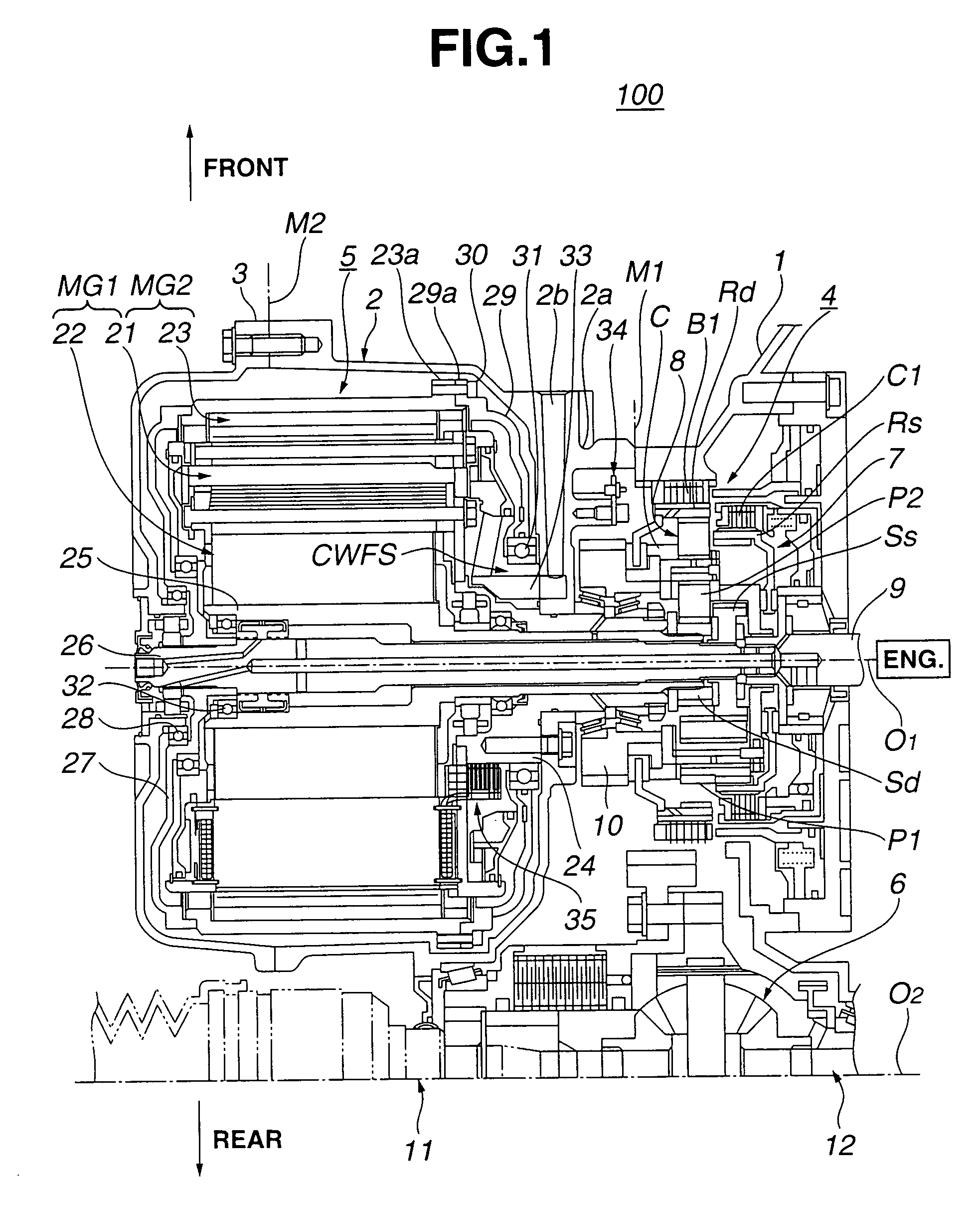
[0018]Referring to FIG. 1, there is shown, but in a sectional manner, a hybrid transmission 100 according to the present invention.

[0019]Hybrid transmission 100 shown is an example that is used as a transaxle for a FF (viz., front engine front drive) type motor vehicle. Thus, in FIG. 1, a transversely mounted engine ENG is positioned at a right side of hybrid transmission 100. That is, in the drawing, an upper side indicates a front part of an associated motor vehicle, a lower side indicates a rear part of the vehicle, a left side indicates a left side of the vehicle and ...


PUM


Abstract

A differential speed change unit is installed in a housing at a position near an engine and arranged coaxial with a common axis, and a two-rotor type motor/generator unit is installed in the housing at a position away from the engine and arranged coaxial with the common axis. The motor/generator unit has inner and outer rotors and a wiring. An inner rotor shaft is connected with the inner rotor to rotate therewith. The inner rotor shaft extends coaxially with the common axis to be operatively connected to the differential speed change unit. An outer rotor shaft is connected with the outer rotor to rotate therewith. The outer rotor shaft extends coaxially with the common axis to be operatively connected to the differential speed change unit. The housing has a split section at which the housing is dividable into two housing parts, and the split section is positioned between the differential speed change unit and the motor/generator unit.

Description

BACKGROUND OF THE INVENTION[0001]1. Field of the Invention[0002]The present invention relates in general to hybrid transmissions for wheeled motor vehicles, and more particularly to the hybrid transmissions of a type that facilitates the work for assembling parts of a differential speed change unit in a housing of the transmission.[0003]2. Description of the Related Art[0004]One of the hybrid transmissions of the above-mentioned type is shown in Japanese Laid-Open Patent Application 2000-014081.[0005]That is, the hybrid transmission of this publication comprises generally a differential speed change unit and a two-rotor type motor / generator unit which are coaxially arranged on a common axis and installed in a common housing. Upon mounting on a vehicle, the transmission is positioned beside an engine in such a manner that the speed change unit is placed between the motor / generator unit and the engine. The engine is operatively connected to given parts of the speed change unit from on...

Claims


Application Information

Patent Timeline
Patent Type & Authority Patents(United States)
IPC IPC(8): B60K6/04B60K6/00F16H3/72F16H3/44H02K7/00B60K1/02B60K1/00B60K6/365B60K6/405B60K6/445B60K6/543B60L50/16
CPCB60K6/365B60K6/405B60K6/445B60K6/543F16H3/728H02K7/006B60K1/02B60K2001/003F16H2037/103F16H2200/2025Y02T10/6239Y02T10/62
Inventor SHIMIZU, HIROFUMINAKANO, MASAKI
Owner NISSAN MOTOR CO LTD
Why Eureka
Try Eureka