

Antenna device and radio communication equipment including the same
- Summary
- Abstract
- Description
- Claims
- Application Information
AI Technical Summary
Benefits of technology
Problems solved by technology
Method used
Image

Examples
Embodiment Construction
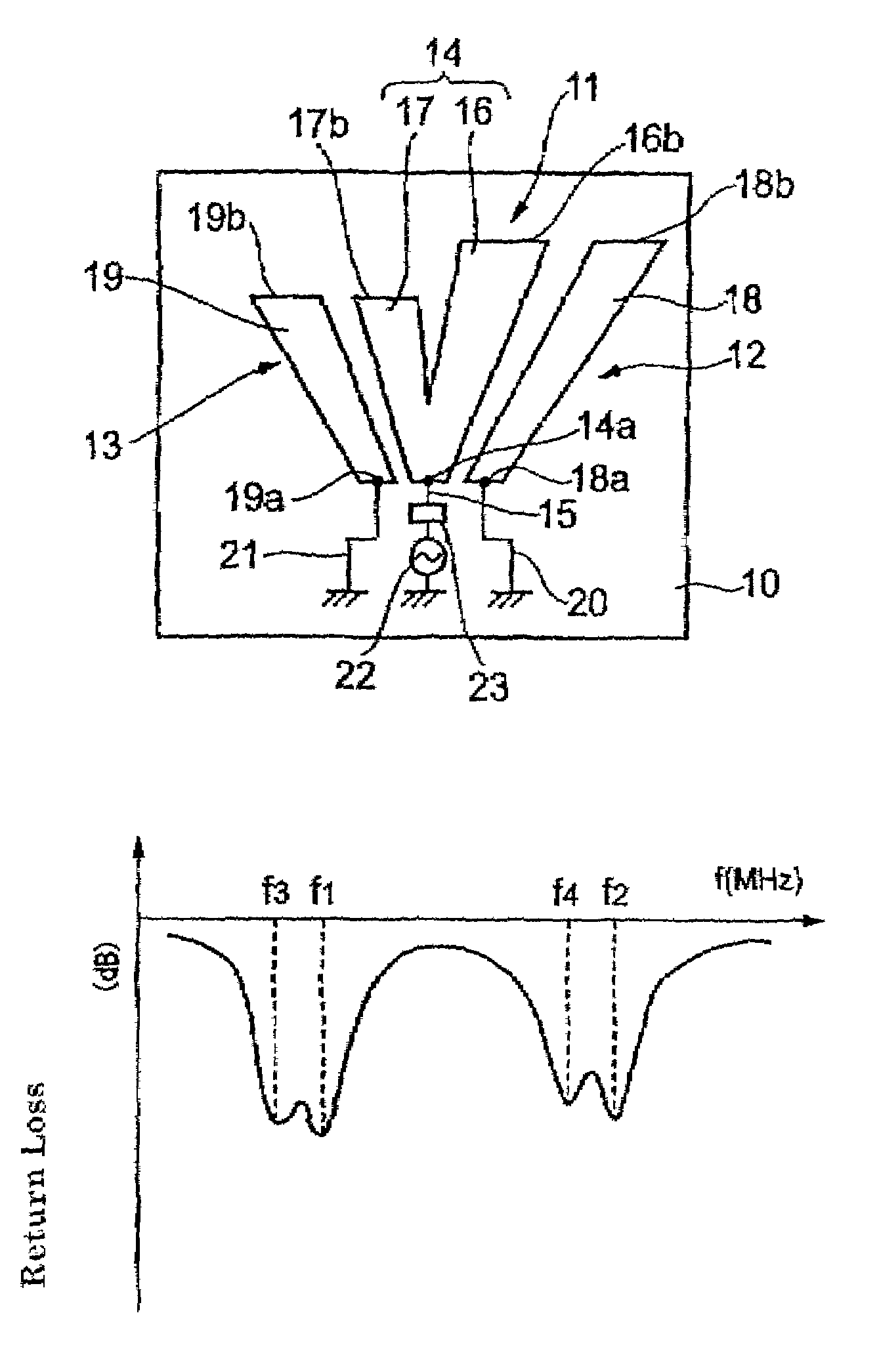
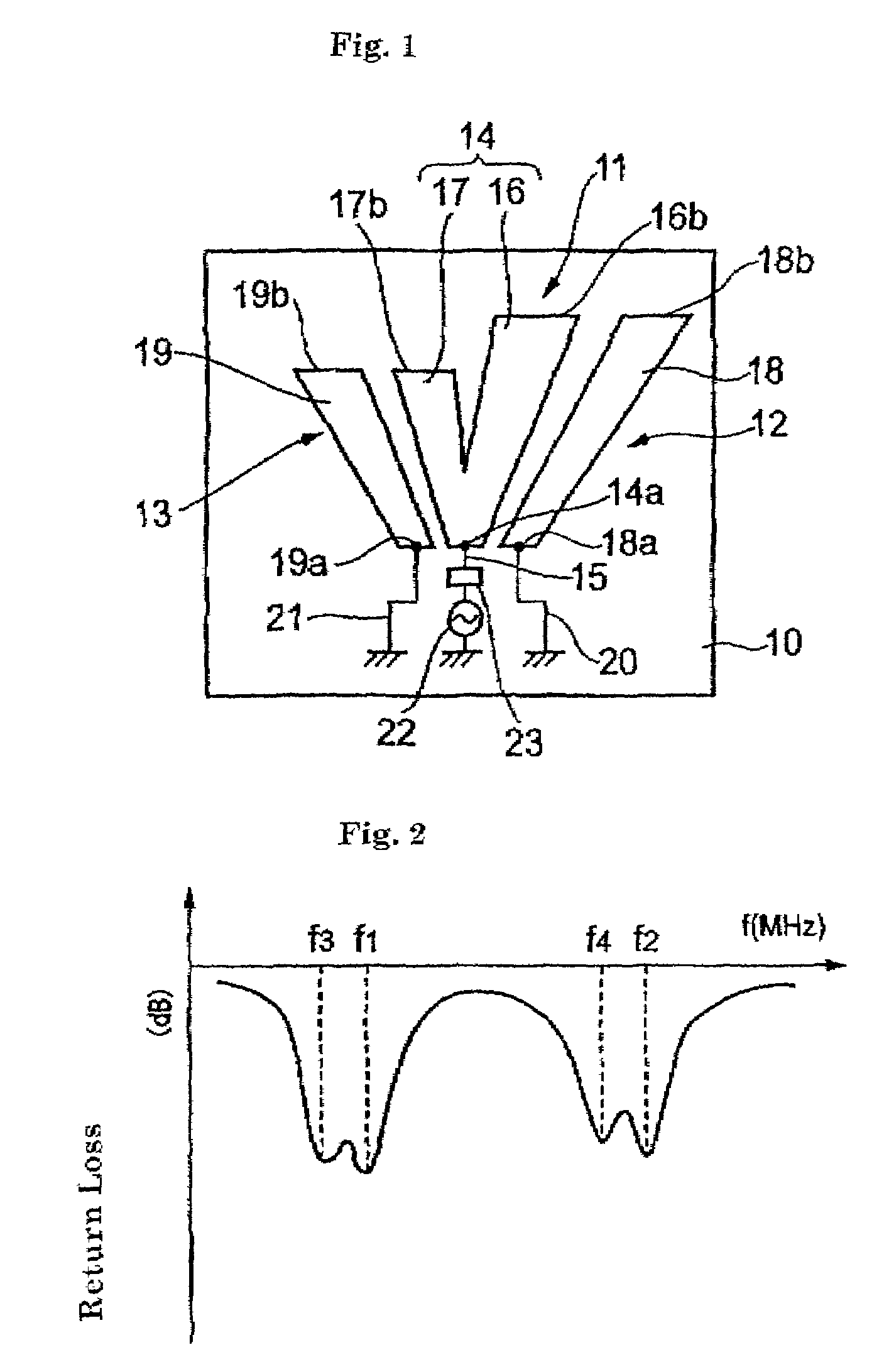
[0065]Hereinafter, preferred embodiments of the present invention will be described with reference to the drawings. FIG. 1 shows the basic configuration of an antenna device according to preferred embodiments of the present invention. FIG. 2 shows the characteristic curve of the antenna device of FIG. 1 which illustrates the double resonance of the device. For simplification, a preferred embodiment including two feed elements and two non-feed elements will be described by way of an example.
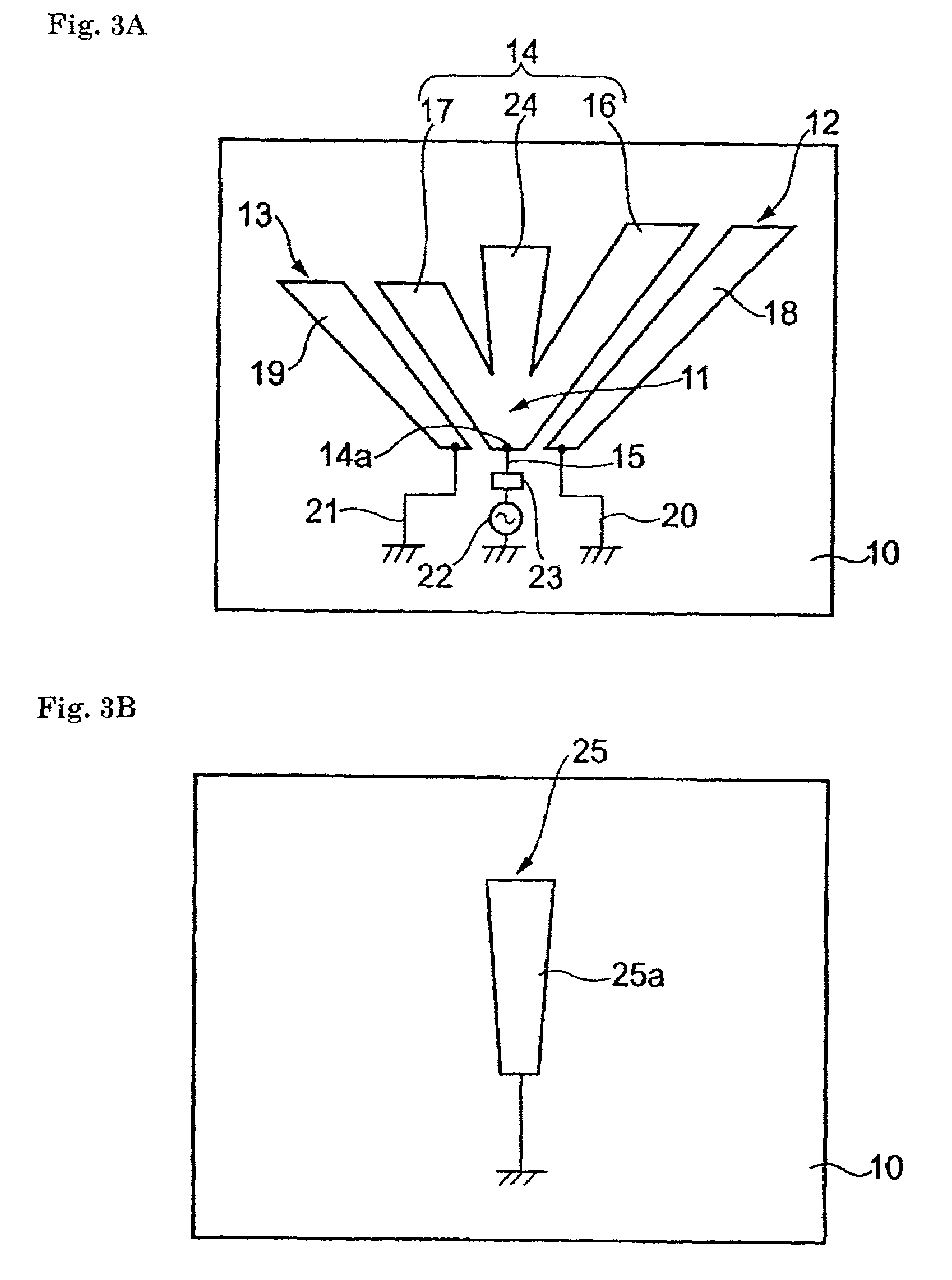
[0066]In FIG. 1, a substrate 10 is formed of a dielectric material, and has a rectangular surface. A feed element 11 is provided on the surface of the substrate 10. A non-feed element 12 is provided on the right side of the feed element 11 in the vicinity thereof. Moreover, a non-feed element 13 is provided on the left side of the feed element 11 in the vicinity thereof, and has a resonance frequency different from that of the non-feed element 12.
[0067]The feed element 11 includes a feed radiation...
PUM
 Abstract
Description
Claims
Application Information