Optical stitch regulator system

a regulator system and optical technology, applied in the field of optical stitch regulator system, can solve the problems of requiring external wiring and encoders which can be damaged, requiring multiple wheel encoders, and utilized on a straight and smooth surface, and achieve the effect of efficient regulating stitch length and stitch frequency

Inactive Publication Date: 2005-11-01
DUVAL RICHARD J
View PDF5 Cites 53 Cited by
  • Summary
  • Abstract
  • Description
  • Claims
  • Application Information

AI Technical Summary

Benefits of technology

[0009]In view of the foregoing disadvantages inherent in the known types of stitch regulators now present in the prior art, the present invention provides a new optical stitch regulator system construction wherein the same can be utilized for efficiently regulating the stitch length and stitch frequency of a sewing machine.

Problems solved by technology

One of the problems with conventional stitch regulators is that they require multiple wheel based encoders—one for each axis of movement.
A further problem with conventional stitch regulators is that they must be utilized upon a straight and smooth surface.
A further problem with conventional stitch regulators is that they are dependent upon equipment installed upon the XY carriages to provide the motion feedback of the piece being sewn.
Another problem with conventional stitch regulators is that they require external wiring and encoders which can be damaged.
Conventional stitch regulators utilize mechanical feedback devices that are dependent upon the XY carriages of the sewing machine and that can be damaged during operation of the sewing machine.

Method used


Image

  • Optical stitch regulator system
  • Optical stitch regulator system
  • Optical stitch regulator system

Examples


Embodiment Construction

A. Overview

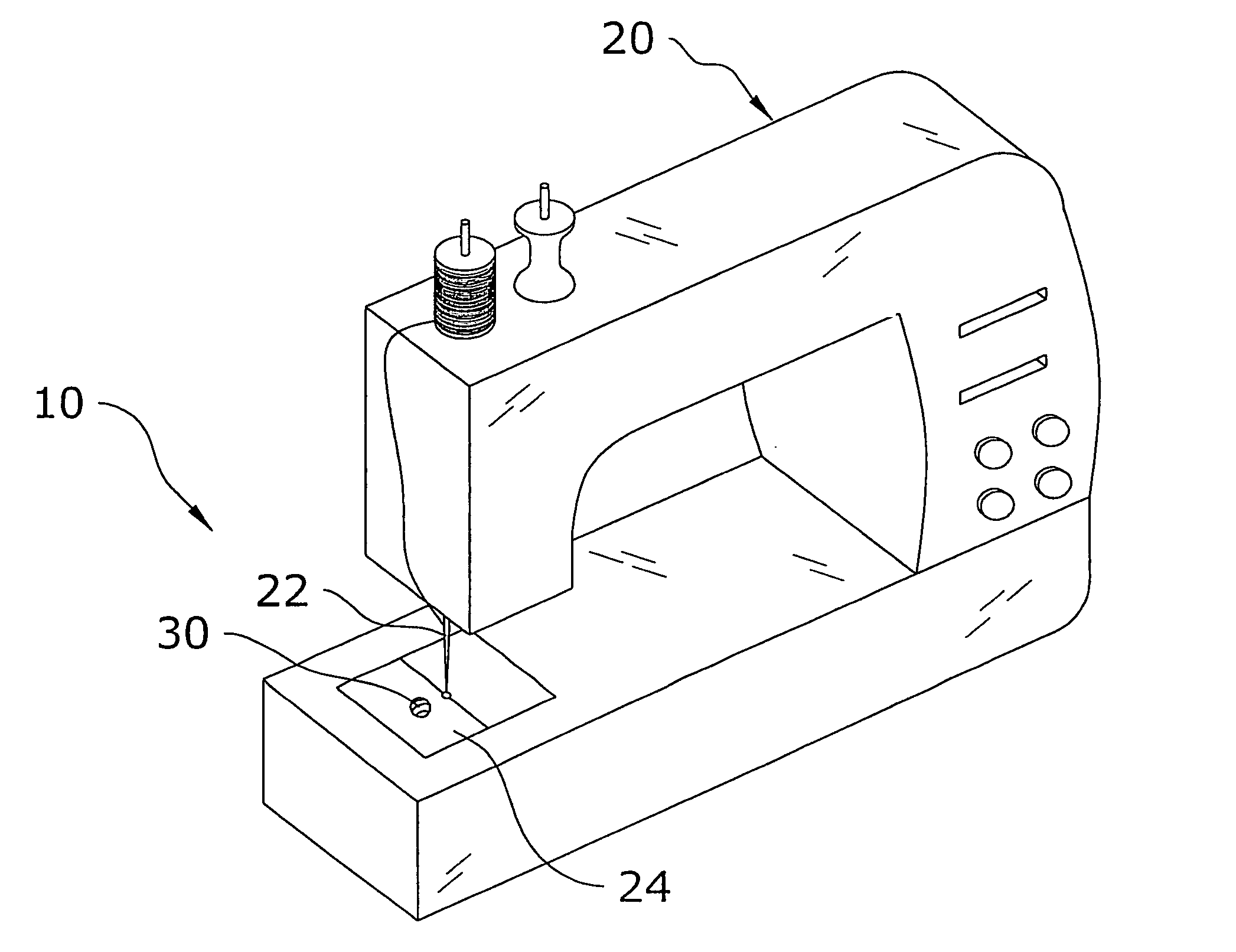
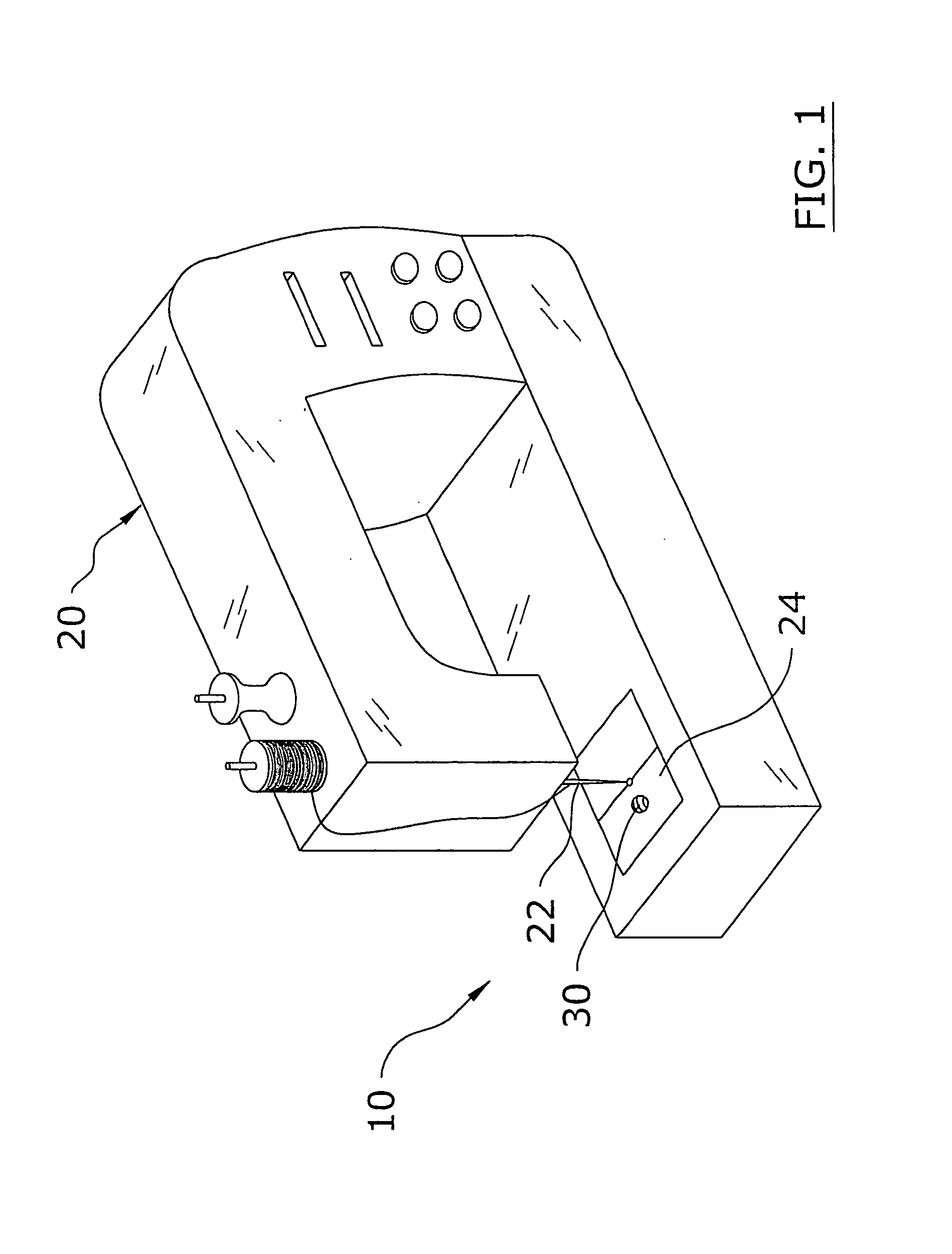
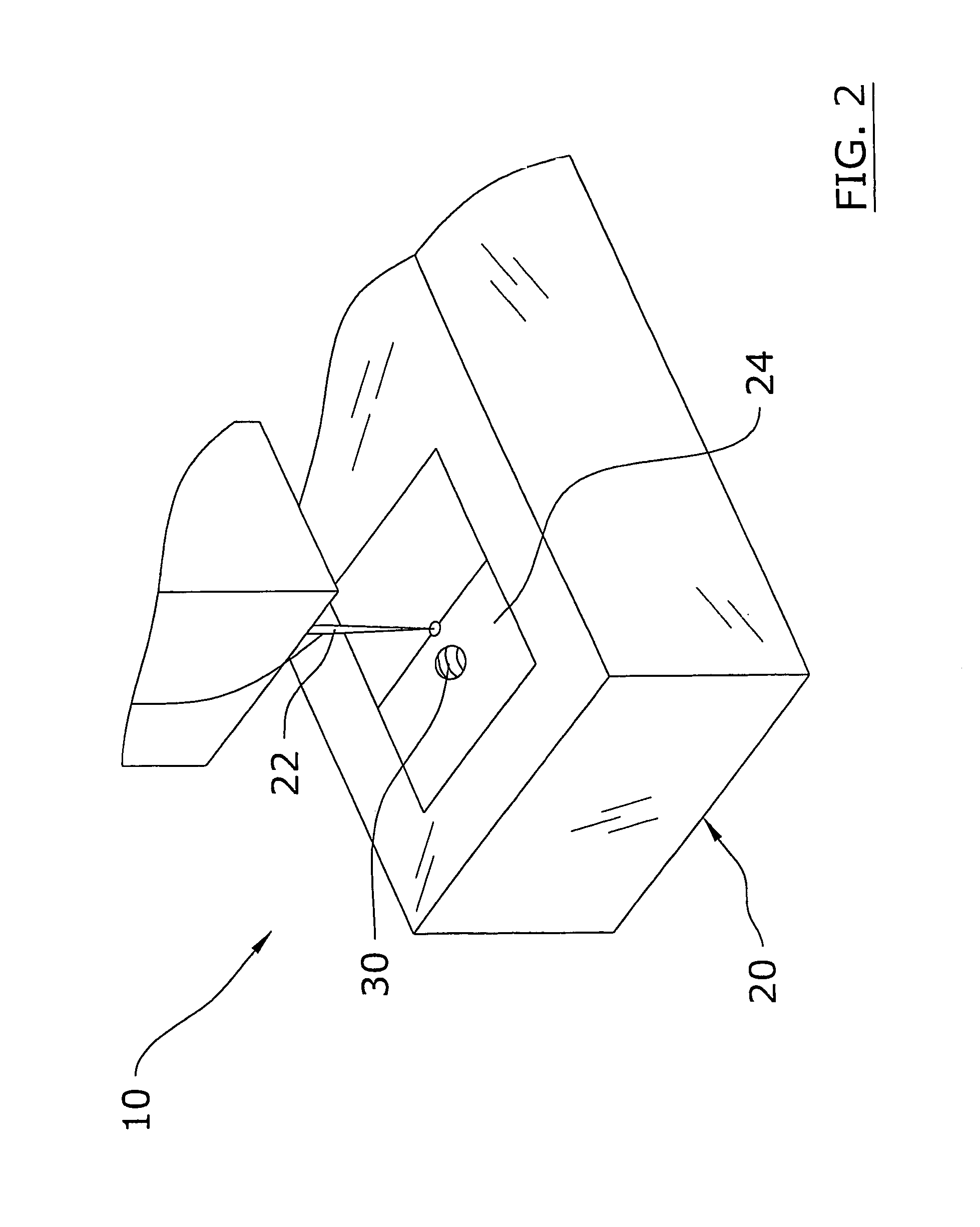
[0032]Turning now descriptively to the drawings, in which similar reference characters denote similar elements throughout the several views, FIGS. 1 through 9 illustrate an optical stitch regulator system 10, which comprises an optical sensor 30 within or external of the sewing platform 24 of a sewing machine 20 for sensing the motion of the fabric 12 being sewn. The motion data is communicated to a control unit 40 which communicates with the sewing machine 20 for controlling the stitch length and frequency.

B. Sewing Machine

[0033]The sewing machine 20 may be comprised of any conventional sewing machine 20 (e.g. personal, commercial, industrial). The sewing machine 20 may have various structures and functionality other than shown in FIGS. 1 through 7 of the drawings. For example, the sewing machine 20 may be comprised of a long arm quilting machine wherein the needle 22 is moved relative to the fabric 12 by utilizing carriages to move the needle 22 relative to a fabric 12....


PUM


Abstract

An optical stitch regulator system for efficiently regulating the stitch length and stitch frequency of a sewing machine. The optical stitch regulator system includes at least one optical sensor within or external of the sewing platform of a sewing machine for sensing the motion of the fabric being sewn. The motion data is communicated to a control unit which communicates with the sewing machine for controlling the stitch length and frequency.

Description

CROSS REFERENCE TO RELATED APPLICATIONS[0001]Not applicable to this application.STATEMENT REGARDING FEDERALLY SPONSORED RESEARCH OR DEVELOPMENT[0002]Not applicable to this application.BACKGROUND OF THE INVENTION[0003]1. Field of the Invention[0004]The present invention relates generally to sewing machine stitch regulators and more specifically it relates to an optical stitch regulator system for efficiently regulating the stitch length and stitch frequency of a sewing machine.[0005]2. Description of the Related Art[0006]Conventional stitch regulators for sewing machines have been in use for years. Conventional stitch regulators utilize wheel based encoders that are attached to the frame of the sewing machine.[0007]One of the problems with conventional stitch regulators is that they require multiple wheel based encoders—one for each axis of movement. A further problem with conventional stitch regulators is that they must be utilized upon a straight and smooth surface. A further probl...

Claims


Application Information

Patent Timeline
Patent Type & Authority Patents(United States)
IPC IPC(8): D05B69/00D05B21/00D05B69/36D05B19/14D05B69/18D05B73/12
CPCD05B19/14D05B69/18D05B73/12
Inventor DUVAL, RICHARD J.
Owner DUVAL RICHARD J
Why Eureka
Try Eureka